Spectrum+Operating+Manual.pdf - 第179页
S2-9 XXX Se ri es Dispensing Sys te m IOM Man ual Parts Replacement © 2023 Nordson C orpor ation 8-27 8.15.2 Replacing the Front EMO Actuator Switch To remove the front EMO actua tor switch (F igure 8- 21 ): 1. Perform a…

S2-9XXX Series Dispensing System IOM Manual Parts Replacement
8-26 © 2023 Nordson Corporation
To install the control panel (Figure 8-20):
1. If necessary, replace the failed switches, see 8.13.2 Replacing the Front EMO Actuator
Switch, 8.13.3 Replacing the ON Switch, or 8.13.4 Replacing the OFF Switch.
2. Install the control panel onto the dispensing system.
Make sure to support the control panel or wiring and cable connector damage may
occur.
3. Install the four (4) screws securing the control panel to the dispensing system.
4. Replace the dispense station cover, see 8.8 Removing and Installing the Dispense Station
Cover.
5. Close the dispensing area door.
S2-9XXX Series Dispensing System IOM Manual Parts Replacement
© 2023 Nordson Corporation 8-27
8.15.2 Replacing the Front EMO Actuator Switch
To remove the front EMO actuator switch (Figure 8-21):
1. Perform a service shutdown, see 2.14 Service Shutdown.
2. Remove the control panel, see 8.13.1 Removing and Installing the Control Panel.
3. Disconnect the power control cables from the EMO contact block switch.
4. From rear of the control panel using the switch mounting tool, remove the nut securing the
EMO actuator switch.
5. Remove the EMO actuator switch and EMO switch guard from the front of the control
panel.
Item
Description
Item
Description
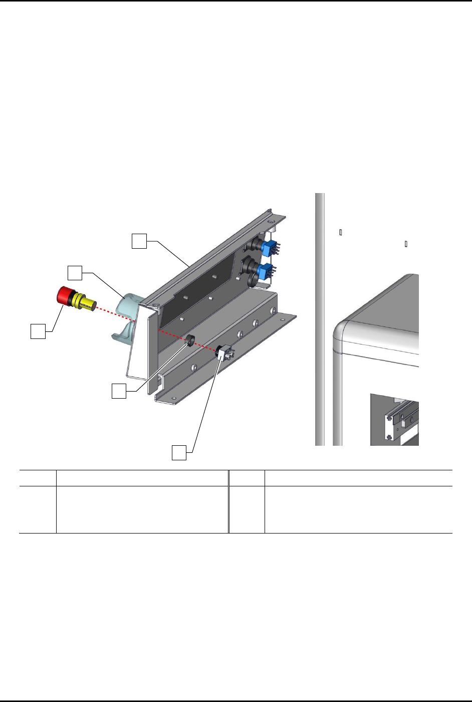
1 Front Control Panel 4 EMO Nut (included with Item 15)
2
EMO Switch Guard
5
Contact Block (Item 15)
3 EMO Actuator Switch (Item 15)
Figure 8-21 Replacing the Front EMO Actuator Switch (Wiring Not Shown for Clarity)
3
2
1
4
5
S2-9XXX Series Dispensing System IOM Manual Parts Replacement
8-28 © 2023 Nordson Corporation
To install the front EMO actuator switch (Figure 8-21):
1. Install the EMO actuator switch through the front of the control panel.
2. Apply plastic thread locker onto the threads of the EMO nut.
3. Install a new EMO nut from the rear of the control panel onto the EMO actuator switch.
4. Tighten the EMO nut with the switch mounting tool.
5. Connect the EMO switch contact block to the EMO actuator switch.
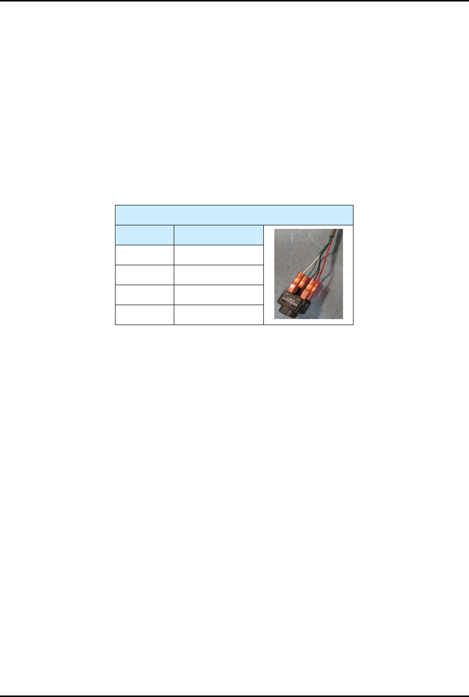
6. Connect the power control cables to the EMO contact block switch, see Table 8-1.
7. Reinstall the control panel, see 8.13.1 Removing and Installing the Control Panel.
Table 8-1 Power Control Cable Connections (EMO Switch)
EMO Switch
Contact # Color
11 Black
12 Red
21 White
22 Green