Spectrum+Operating+Manual.pdf - 第78页
S2-9 XX X Se ri es Disp ensi n g Syst em IOM Man ual Calibration and Adjus tment 5-2 © 2023 Nordson Corporatio n 5.4 Focusi ng the Camera NOTE This p roced ure assume s the dispensing s y st em has been powered on , Fl…

© 2023 Nordson Corporation 5-1
5 Calibration and Adjustment
5.1 Overview
After initial installation or if any hardware changes have been made, certain dispensing system
components may need to be calibrated or adjusted. This section covers the following topics:
• Focusing the Camera
• Adjusting the Service Station Height
• Calibrating the Camera • Adjusting the Height Sensor Probe
(Option)
• Calibrating the Scale
• Initializing the Digital Gauges
• Adjusting the Z-Head Counterbalance Force
• Calibrating the Heaters
• Adjusting the Board Sensors
• Controlled Process Heat
• Calibrating the E/P Controllers • Adjusting Manual Airflow for
Impingement Heaters
• Adjusting the Air Pressure
• Adjusting the Lift Table Speed
5.2 Safety First
Operation of your dispensing system involves heat, air pressure, electrical power, mechanical devices,
and the use of hazardous materials. Read this manual in its entirety before attempting any system or
component operation. It is essential for all personnel working on or around the dispensing system to fully
understand the hazards, risks, and safety precautions associated with operating the system. When properly
operated and maintained, the dispensing system is safe and reliable. See Section 2 - Safety for additional
information.
WARNING! The procedures in this section should only be performed by a trained
service technician.
5.3 Record Keeping
The type of maintenance performed (such as preventive and parts replacement) should be recorded in
maintenance records for the dispensing system. Dates, part numbers/serial numbers of replaced parts,
names of technicians, and other pertinent data should be recorded.
S2-9XXX Series Dispensing System IOM Manual Calibration and Adjustment
5-2 © 2023 Nordson Corporation
5.4 Focusing the Camera
NOTE This procedure assumes the dispensing system has been powered on, Fluidmove is
running, and a representative substrate is available to teach the focal plane.
Tools and Materials Needed:
• 3 mm hex key
To focus the camera:
1. In the Fluidmove Programming Window, click the
Load a Board icon.
The conveyor will transport the substrate to the dispense station and the lift mechanism
will lift it off the conveyor belt. This establishes the focal plane.
2. In the Fluidmove Main Window, click on
Jog.
The Jog Window opens.
Refer to the Fluidmove User Guide or Fluidmove Online Help
for the Jog Window operation.
3. Click on
Video.
The Video Window opens.
4. Position the camera over a fiducial or an easily recognized feature on the substrate.
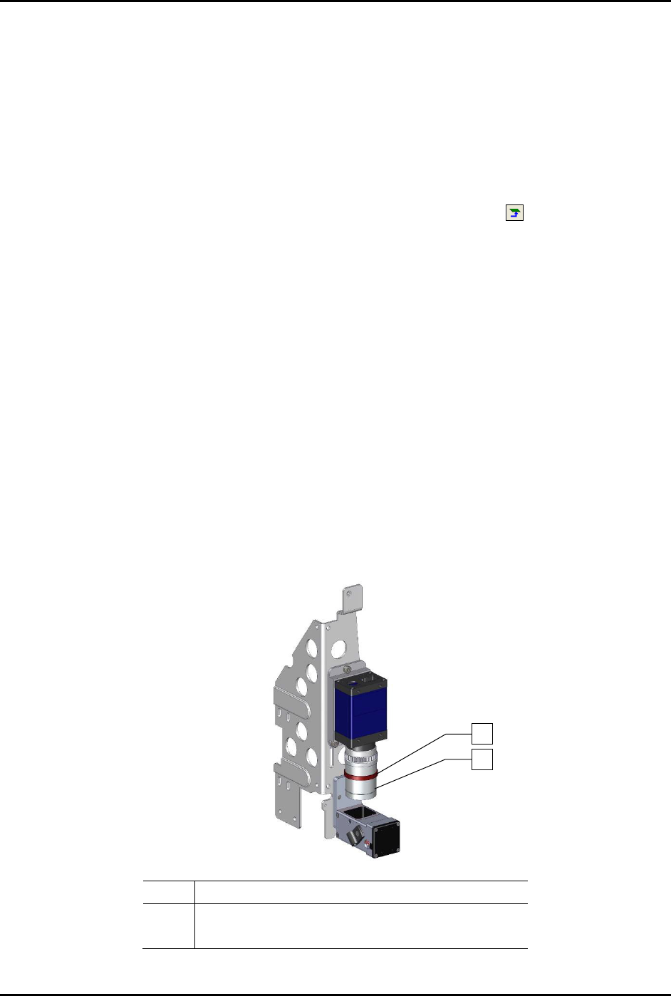
5. Loosen the locking ring on the camera lens (Figure 5-1).
6. Turn the middle section of the camera lens, clockwise or counterclockwise, until the middle
of the range of travel is reached. This will allow for fine focus after the camera is adjusted
for rough focus.
7. Tighten the locking ring.
Item Description
1 Locking Ring
2 Middle Section
Figure 5-1 Focusing the Camera
1
2
S2-9XXX Series Dispensing System IOM Manual Calibration and Adjustment
© 2023 Nordson Corporation 5-3
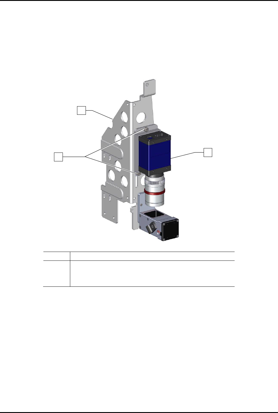
8. For rough focus, perform the following steps:
a. Hold the camera and use a 3 mm hex key to loosen the three (3) screws securing the
camera to the bracket (Figure 5-2).
b. Slowly move the camera up and down in the bracket.
c. When a sharp image is obtained in the Video Window, hold the camera and tighten the
three (3) screws securing the camera to the bracket using a 3 mm hex key.
Item
Description
1
Bracket
2
Screw (Third screw is located opposite of lower left screw)
3
Camera (Item 55)
Figure 5-2 Rough Focus
1
3
x3
2