Spectrum+Operating+Manual.pdf - 第107页
S2-9 XXX Se ri es Dispensing Sys te m IOM Man ual Calibration and Adjustme nt © 2023 Nordson C orporatio n 5-31 5.15.2 CpH C ool Do wn The c ool d own feature wil l allow the op erator to select which sta tions should b …
S2-9XXX Series Dispensing System IOM Manual Calibration and Adjustment
5-30 © 2023 Nordson Corporation
9. Click on OK to close the Heater Control Window.
10. Click on
Main to return to the Fluidmove Main Window.
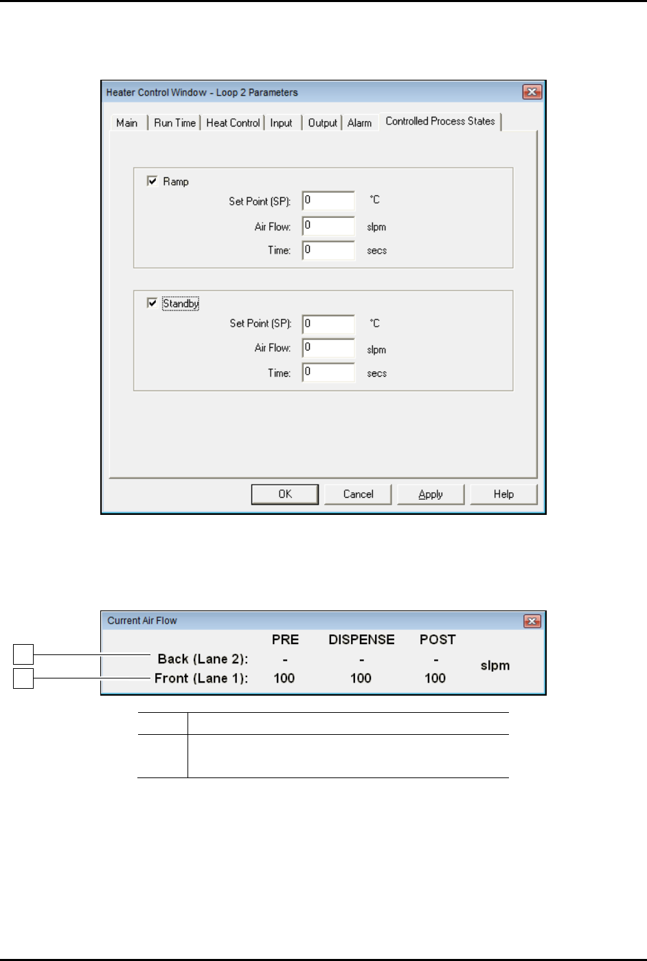
Figure 5-32 Heater Control Window - Controlled Process States
11. You may press [Ctrl + A] in any Fluidmove window to toggle the Current Air Flow toolbar
ON and OFF (Figure 5-37).
Item
Description
1
Conveyor 1 Impingement Airflow
2 Conveyor 2 Impingement Airflow
Figure 5-33 Current Air Flow Toolbar
1
2
S2-9XXX Series Dispensing System IOM Manual Calibration and Adjustment
© 2023 Nordson Corporation 5-31
5.15.2 CpH Cool Down
The cool down feature will allow the operator to select which stations should be cooled down before
working on or removing a heater module. The heater will be shut off and maximum air flow will be
applied for a given amount of time specified by the operator.
To cool down the heaters:
1. In the Fluidmove Main window, click on
Run a Program.
The Production Window opens.
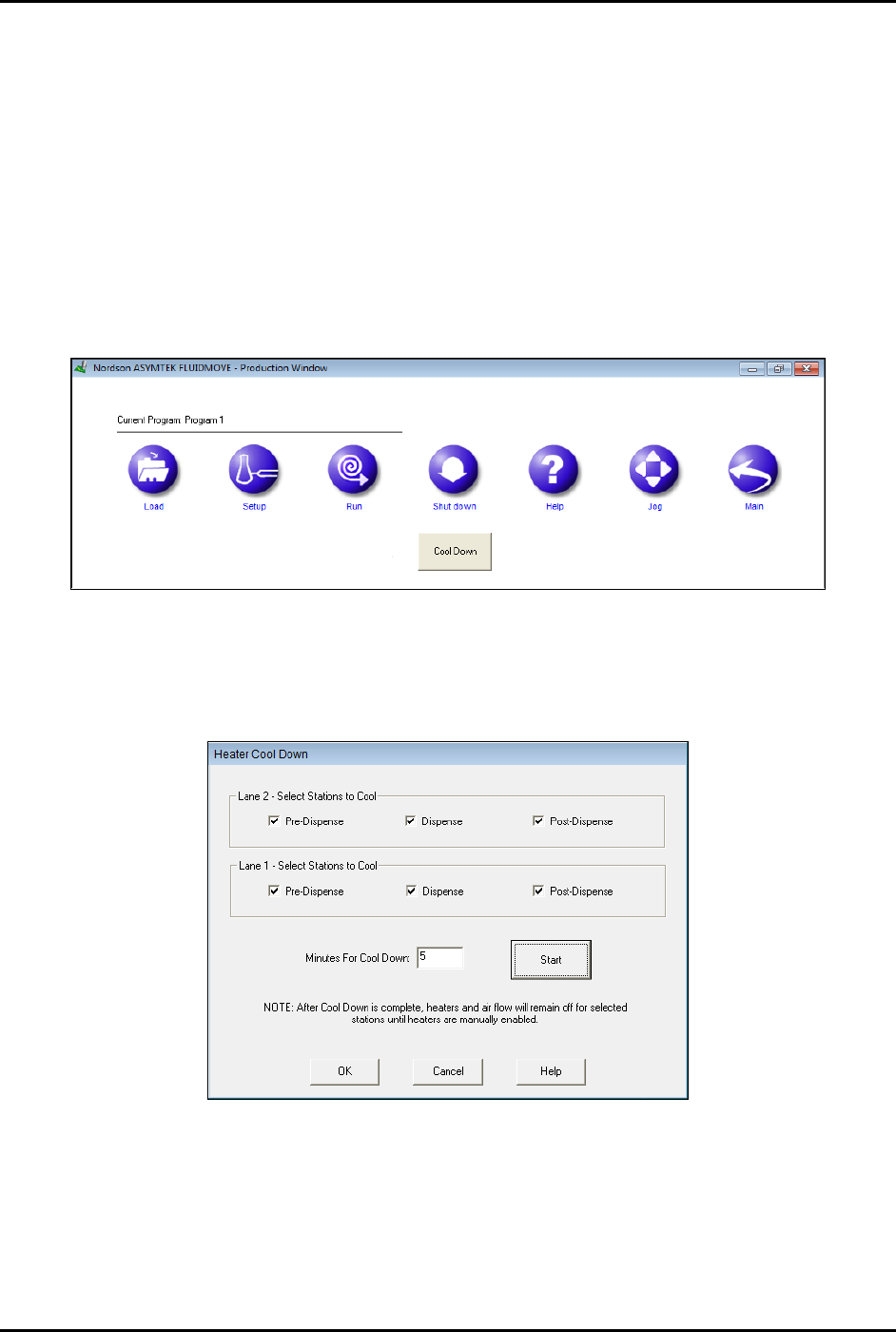
2. Click on
Shutdown.
The Cool Down button appears (Figure 5-38).
Figure 5-34 Fluidmove Main Window - Cool Down Button
3. Click on Cool Down.
The Heater Cool Down window opens (Figure 5-39).
Figure 5-35 Heater Cool Down Window
4. Select the desired stations and enter a cool down time.
5. Click
Start to begin the cooling process.
6. Click on
Cancel to stop the cooling process before the time expires.

S2-9XXX Series Dispensing System IOM Manual Calibration and Adjustment
5-32 © 2023 Nordson Corporation
5.16 Adjusting Manual Airflow for Impingement Heaters
NOTES This procedure applies to systems equipped with impingement heat and manual flow
controls.
This procedure does not apply to systems configured with optional Controlled Process
Heat (CpH), see 5.15 Controlled Process Heat.
Airflow to impingement heaters is adjusted by turning the applicable flowmeter adjustment knob located
in the lower front cabinet door. Airflow is read on the gauge on the front of the flowmeter (Figure 5-40).
Factors to be considered when determining the airflow include the following:
• Maximum airflow is 4.0 SCFM.
• Size, weight, and securing of the workpiece (high airflow can cause
movement/misalignment).
• Effect of airflow on the time it takes to heat the workpiece to dispensing temperature.
• Effect of airflow on how fast the heat tooling reaches/maintains steady-state temperature.
• Ambient temperature of the dispensing area and its effect on dispensing fluid properties
(pot life, viscosity, cure time).
To adjust the flowmeters (Figure 5-40):
1. Locate the impingement air valve and flowmeters in the front cabinet of the dispensing
system.
Depending on system configuration, there can be up to six (6) flowmeters (pre-queue,
dispense, and post-queue for Conveyor 1 and Conveyor 2).
The pre- and post-queue flowmeters are located below the pre- and post-queue stations.
2. Open the impingement air valve by turning the handle counterclockwise so that it is parallel
with the airline and listen for leaks.
If there is an air leak, identify the source, shut off the air valve, and fix the leak before
proceeding.
3. While monitoring the readouts on all flowmeters, turn the flowmeter adjustment knobs
counterclockwise until maximum airflow is achieved.
The flow indicators should show an increase in airflow.
4. While monitoring the readouts on all flowmeters, turn the flowmeter adjustment knobs
clockwise to lessen the flow.
The flow indicators should show a decrease in airflow.
5. Restore maximum airflow and open the dispensing area do
or. Verify air is coming out of
the holes in impingement heater at each conveyor station.
6. If air is not flowing out of the heater, check the pneumatic connections.