Spectrum+Operating+Manual.pdf - 第124页
S2-9 XX X Se ri es Disp ensi n g Syst em IOM Man ual Maintenance 6-12 © 2023 Nordson Corporatio n 6.9.2 Y-Axis Cable Cover This procedure is for bot h left or right Y-axis cable covers. To remove the Y -a xis covers ( Fi…
S2-9XXX Series Dispensing System IOM Manual Maintenance
© 2023 Nordson Corporation 6-11
6.9 Removing and Installing the Axis Covers
In order to lubricate the cables and linear guides and to tension the cables, it will be necessary to remove
the X-axis, Y-axis, and rear cable covers.
Tools and Materials Needed:
• Hex Wrench Set
WARNING! Ensure the dispensing system has been completely shutdown before attempting to
remove any panel.
6.9.1 X-Axis Cable Cover
To remove the X-axis covers (Figure 6-6):
1. Perform a service shutdown, see 2.14 Service Shutdown.
2. Open the dispensing area door.
3. Remove the four (4) screws securing the X-axis cable cover to the X-axis.
4. Remove the X-axis cable cover.
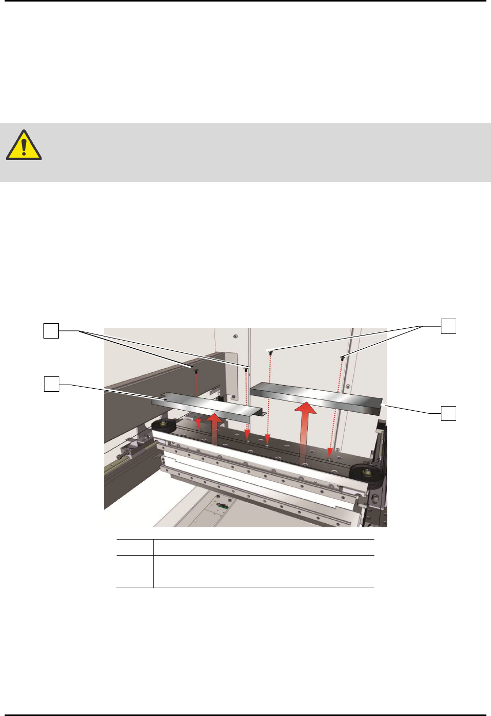
Item Description
1 X-Axis Cable Cover
2 Screws (4)
Figure 6-6 Removing the X-Axis Covers
To install the X-axis cable cover (Figure 6-1):
1. Install the four (4) screws securing the X-axis cable cover to the X-axis.
2. Torque the four (4) screws to 2.8 Nm (25 in-lbs).
3. Close the dispensing area door.
2
1
1
2
S2-9XXX Series Dispensing System IOM Manual Maintenance
6-12 © 2023 Nordson Corporation
6.9.2 Y-Axis Cable Cover
This procedure is for both left or right Y-axis cable covers.
To remove the Y-axis covers (Figure 6-7):
1. Perform a service shutdown, see 2.14 Service Shutdown.
2. Open the dispensing area door.
3. Removing the top cover, see 8.7 Removing and Installing the Top Cover and Components.
4. Remove the three (3) screws securing the Y-axis cable cover to the Y-axis.
5. Remove the Y-axis cable cover.
Item
Description
1 Y-Axis Cable Cover
2 Screws (3)
Figure 6-7 Removing the Y-Axis Covers
To install the Y-axis cable cover (Figure 6-7):
1. Install the three (3) screws securing the Y-axis cable cover to the Y-axis.
2. Torque the three (3) screws to 5.6 Nm (50 in-lbs).
3. Install the top cover, see 8.7 Removing and Installing the Top Cover and Components.
4. Close the dispensing area door.
2
1
S2-9XXX Series Dispensing System IOM Manual Maintenance
© 2023 Nordson Corporation 6-13
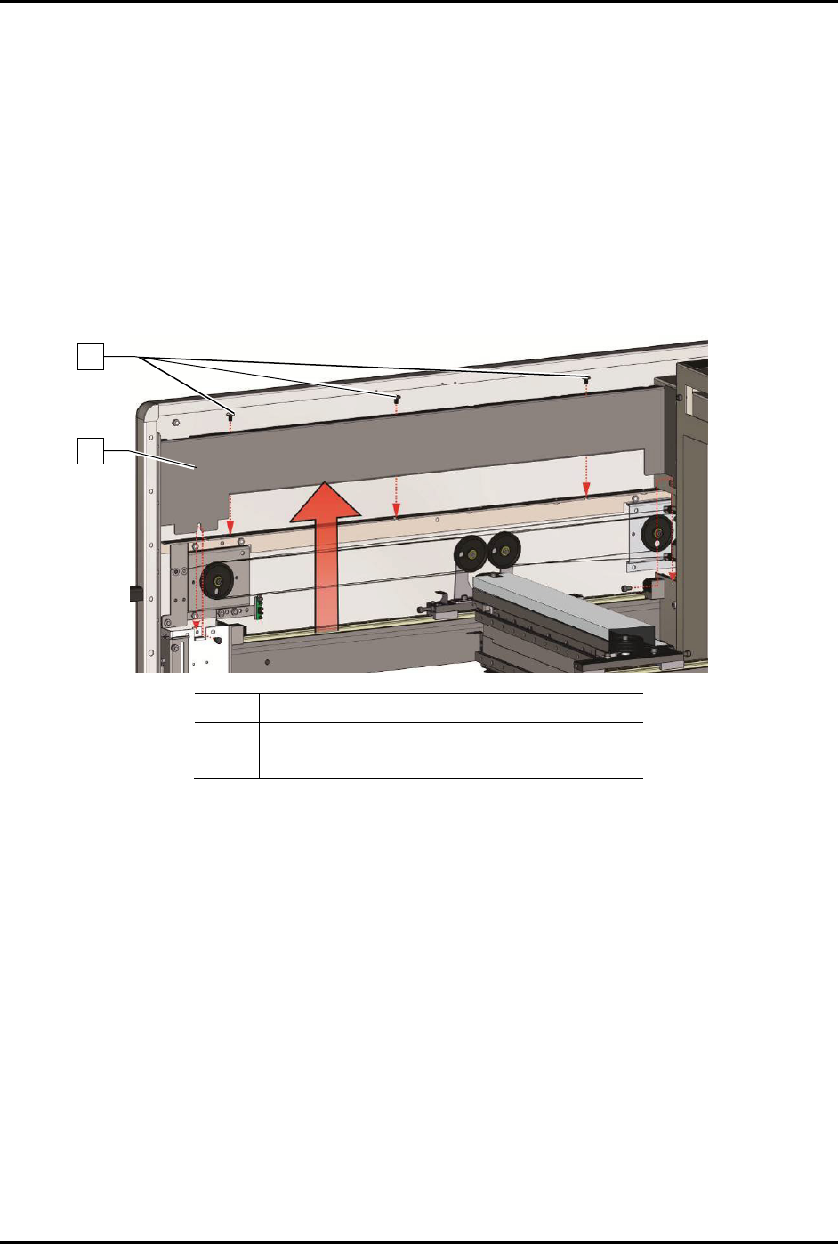
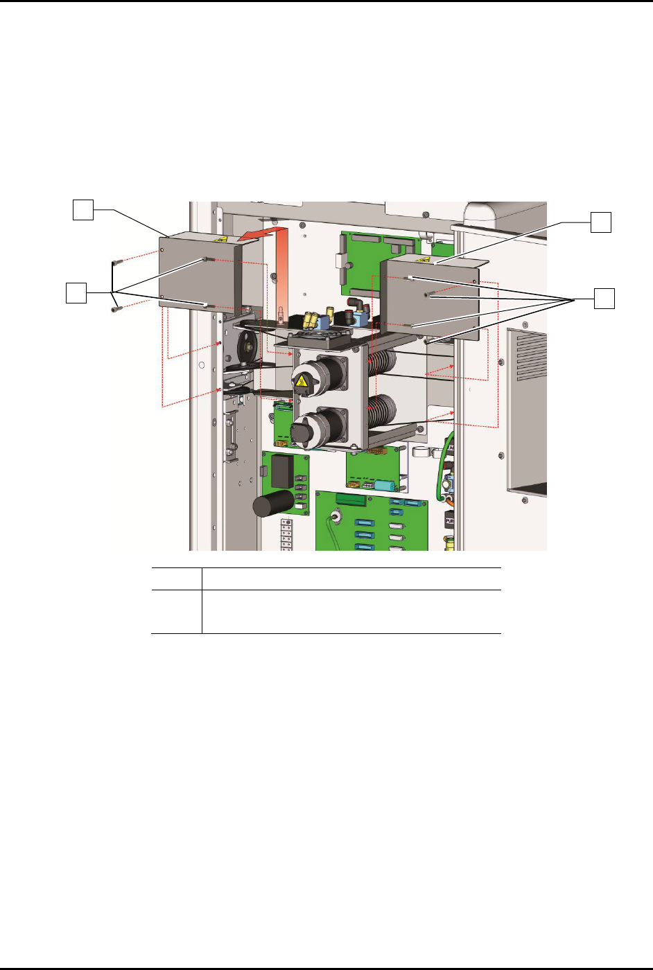
6.9.3 Rear Cable Cover
To remove the rear cable covers (Figure 6-8):
1. Perform a service shutdown, see 2.14 Service Shutdown.
2. Open the rear dispensing area door.
3. Remove the eight (8) screws securing the rear cable covers to the dispensing system.
4. Remove the rear cable covers.
Item
Description
1 Screws (8)
2
Rear Cable Covers
Figure 6-8 Removing the Rear Cable Covers
To install the rear cable covers (Figure 6-8):
1. Install the eight (8) screws securing the rear cable covers to the dispensing system.
2. Torque the eight (8) screws to 2.8 Nm (25 in-lbs).
3. Close the rear dispensing area door.
2
1
2
1