Spectrum+Operating+Manual.pdf - 第201页
S2-9 XXX Se ri es Dispensing Sys te m IOM Man ual Parts Replacement © 2023 Nordson C orpor ation 8-49 8.18.3 P anel Mounted Fu ses These glas s fuses ar e located on th e f ront panel of the c onveyor / h eater mod ul e.…
S2-9XXX Series Dispensing System IOM Manual Parts Replacement
8-48 © 2023 Nordson Corporation
7. Install the new 5A fuse into the fuse holder.
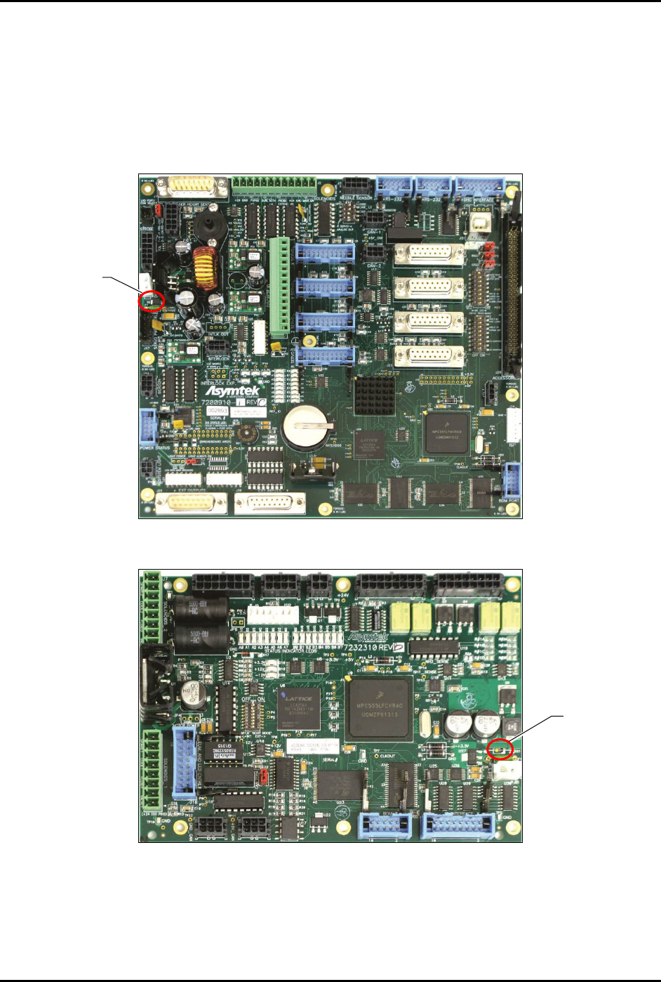
See Figure 8-37 and Figure 8-38 for fuse location.
8. Power on the dispensing system, see 4.3 Powering on the Dispensing System.
9. Verify that the LEDs on the board are now lit.
10. Close the rear dispensing area door.
Figure 8-37 Main PWA Fuse Location
Figure 8-38 PDHC Fuse Location
NOTE The 5A fuses are the only replaceable board fuses. Replacement fuses (Item 59) are
included in Tools & Spares Kit (Item 59).
5A Fuse
5A Fuse
S2-9XXX Series Dispensing System IOM Manual Parts Replacement
© 2023 Nordson Corporation 8-49
8.18.3 Panel Mounted Fuses
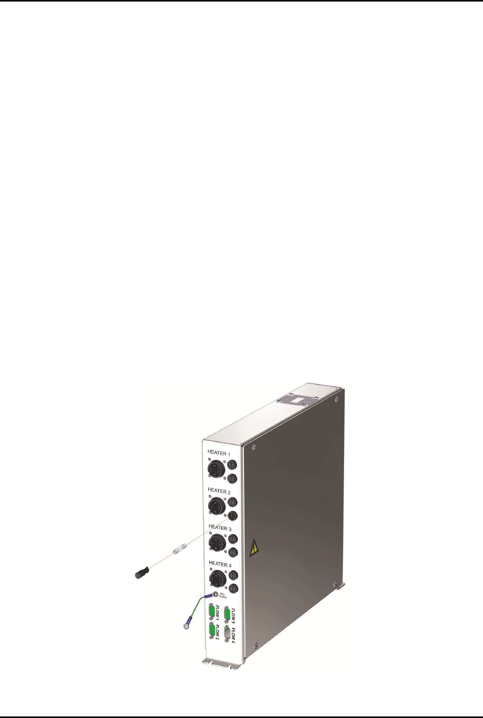
These glass fuses are located on the front panel of the conveyor/heater module. The fuses protect the
module from damage caused by power surges from the heater tooling.
To remove and replace panel-mounted fuses (Figure 8-39):
1. Perform a service shutdown, see 2.14 Service Shutdown.
2. Open the lower front door.
3. With your fingers, gently push in and turn the fuse holder counterclockwise until the head
of the fuse holder pops out enough to allow you to grasp it.
4. Pull the fuse holder out of its socket.
5. Measure the fuse impedance.
6. If the fuse impedance reads infinity, the fuse is bad.
7. Discard the damaged fuse.
8. Verify that you will be installing the correct replacement fuse and then insert the new fuse
into the fuse holder.
9. With your fingers, simultaneously push and twist the fuse holder clockwise into the socket
until it locks into place.
10. Close the lower front door.
11. Power on the dispensing system, see 4.3 Powering on the Dispensing System.
Figure 8-39 Replacing a Panel-Mounted Fuse
S2-9XXX Series Dispensing System IOM Manual Parts Replacement
8-50 © 2023 Nordson Corporation
8.19 Spare Parts List
This section contains a list of item numbers corresponding to the part description. Review the spare parts
listing Excel file for the item number referencing the part number when ordering replacements parts for
the S2-9XXX Dispensing System. Contact Asymtek Technical Support for questions.
Table 8-6 Spare Parts List
Item Number
Description
1
KIT, T1 S2-900 O-RING CNVYR, 1 STN
INSERT, TOP, O-RING, S-920
ASSY, S-9XX O-RING PULLEY
BELT, ORING, 3 X 1265, ESD
KIT, DISP, STN COMMON PARTS
2
KIT, T1 S2-900 O-RING CNVYR, 2 STN
SCREW, M4 X 0.7 SOCKET FLAT X 12
SCREW, M4 X 0.7, SOCKET X 10
SENSOR, BOARD, LOW PROFILE
INSERT, TOP, O-RING, S-920
ASSY, S-9XX O-RING PULLEY
BELT, ORING, 3 X 1730, ESD
ASSY, STOP PIN, S-9XX
KIT, DISP, STN COMMON PARTS
ASSY, RAIL EXT.SET, O-RING BELT
3
KIT, T1 S2-900 O-RING CNVYR, 3 STN
SCREW, M4 X 0.7 SOCKET FLAT X 12
SCREW, M4 X 0.7, SOCKET X 10
SENSOR, BOARD, LOW PROFILE
INSERT, TOP, O-RING, S-920
ASSY, S-9XX O-RING PULLEY
BELT, ORING, 3 X 2195, ESD
ASSY, STOP PIN, S-9XX
KIT, DISP, STN COMMON PARTS
ASSY, RAIL EXT.SET, O-RING BELT
4
KIT, T1 S2-900 4MM BELT CNVYR, 1 STN
SCREW, M4 X 0.7 SOCKET FLAT X 12
RETAINER, BELT, CMP
BELT, FLAT, 3.6 X 1.4 X 1350, ESD
INSERT, TOP, O-RING, S-920
ASSY, S-9XX 4MM BELT PULLEY
KIT, DISP, STN COMMON PARTS
5
KIT, T1 S2-900 4MM BELT CNVYR, 2 STN
SCREW, M4 X 0.7 SOCKET FLAT X 12
SCREW, M4 X 0.7, SOCKET X 10
SENSOR, BOARD, LOW PROFILE
RETAINER, BELT, CMP
BELT, FLAT 3.6 X 1.4 X 1850, ESD
INSERT, TOP, O-RING, S-920