Spectrum+Operating+Manual.pdf - 第96页
S2-9 XX X Se ri es Disp ensi n g Syst em IOM Man ual Calibration and Adjus tment 5-20 © 2023 Nordson Corporatio n 5.11 Adj usting the Service Station H ei ght After t he camer a positio n ha s been adjusted fo r th e par…

S2-9XXX Series Dispensing System IOM Manual Calibration and Adjustment
© 2023 Nordson Corporation 5-19
5.10.4 Adjusting the Vacuum Control
The vacuum control (Figure 5-24) allows low viscosity fluids to be consistently dispensed without
dripping between cycles. The vacuum exerts a negative pressure (suckback) on the fluid, thereby
decreasing dripping.
To adjust the vacuum control:
1. Rotate the knob counterclockwise to increase vacuum pressure and decrease dripping.
2. Rotate the knob clockwise to decrease vacuum pressure.
5.10.5 Setting the Low-Pressure Detection Threshold
This feature allows the user to set the air pressure level at which the software will issue an on-screen low
air pressure error message. Refer to the Fluidmove User Guide or Fluidmove Online Help for
instructions.
S2-9XXX Series Dispensing System IOM Manual Calibration and Adjustment
5-20 © 2023 Nordson Corporation
5.11 Adjusting the Service Station Height
After the camera position has been adjusted for the part set height, the service station height must be
adjusted to bring the ceramic square into focus. The service station can be adjusted upward 1-inch
(25 mm) from the factory set position by performing both rough and fine height adjustments. Each
adjustment will allow 1/2-inch (12.7 mm) of vertical adjustment.
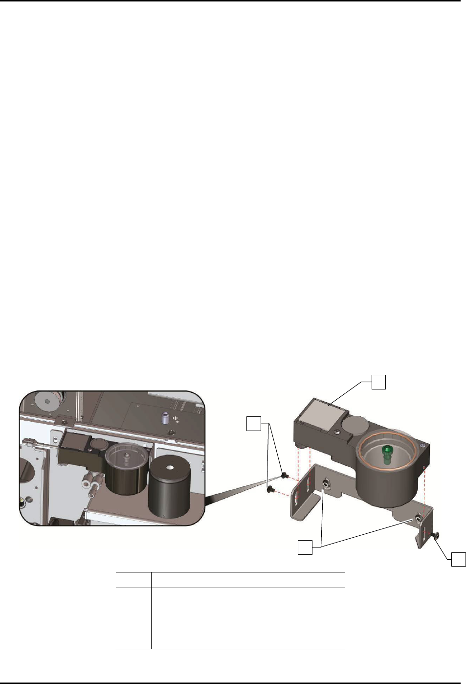
To adjust the service station height (Figure 5-25):
1. Remove the scale cover to gain access to the side mounting screws on the bracket.
2. Loosen the three (3) side mounting screws holding the service station to the bracket.
3. Move the camera over the ceramic tile and adjust the three (3) leveling feet to bring the
ceramic tile into focus.
4. Continue to adjust the leveling feet until all corners of the ceramic square are in focus.
5. Tighten the three (3) side mounting screws.
6. If the leveling feet do not provide enough vertical adjustment to bring the service station
into focus:
a. Remove the three (3) side mounting screws.
b. Slide the service station forward to gain access to the bracket mounting screws.
c. Loosen the two (2) bracket mounting screws, adjust the bracket upwards, and retighten
the two (2) bracket mounting screws.
d. Repeat Step 1 through Step 5 above.
7. When finished, replace the scale cover.
Item
Description
1 Ceramic Tile
2 Side Mounting Screws (3)
3 Bracket Mounting Screws (2)
4 Leveling Feet (not shown)
Figure 5-21 Adjusting the Service Station Height
1
2
2
3
S2-9XXX Series Dispensing System IOM Manual Calibration and Adjustment
© 2023 Nordson Corporation 5-21
5.12 Adjusting the Height Sensor Probe (Option)
The height sensor probe must be adjusted each time a different type of dispensing valve or a different
length of needle is installed.
To adjust the height sensor probe (mechanical/tactile height sensor):
1. Power on the dispensing system, see 4.3 Powering on the Dispensing System.
2. Start the Fluidmove software. Refer to the Fluidmove User Guide or Fluidmove Online
Help.
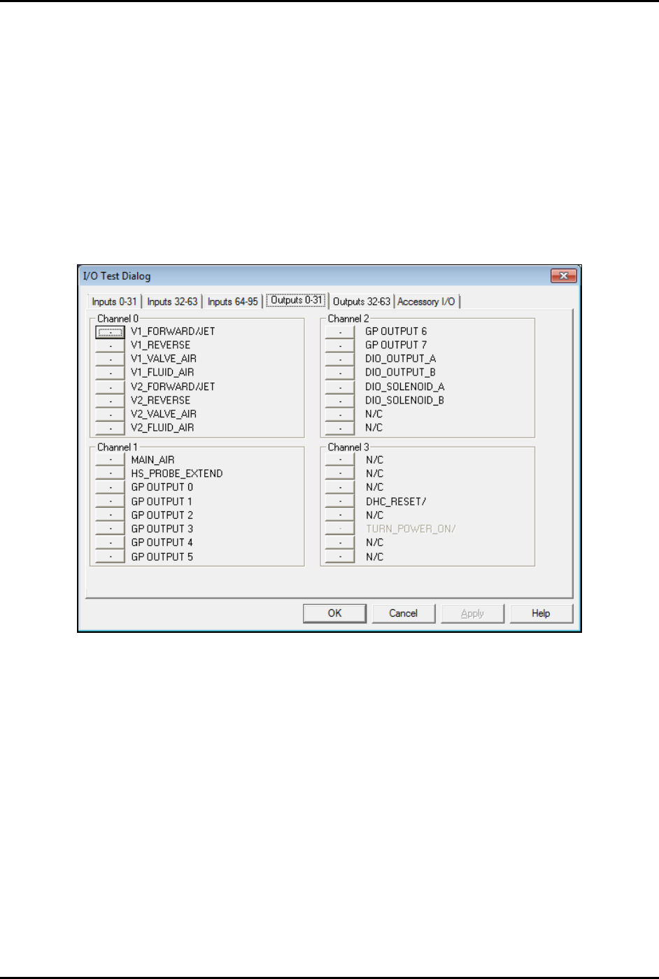
3. Select
Tools > I/O Test > Dispenser from the Fluidmove Main Menu.
The I/O Test Dialog window opens (Figure 5-26).
Figure 5-22 I/O Test Dialog
4. Click on HS_PROBE_EXTEND to extend the height sensor probe.
The bit should change from 0 to 1.
5. Manually move the dispensing head down to provide access to the height sensor
locking screws.
6. Loosen the two (2) height sensor locking screws (Figure 5-27A).
7. Move the probe to the desired location; approximately 6 mm below the nozzle or needle tip
in the gear down position (Figure 5-27B and Figure 5-27C).
8. Do not over-tighten, tighten the two (2) height sensor locking screws.