Spectrum+Operating+Manual.pdf - 第209页
© 2023 Nordson C orporation 9-1 9 S pecificatio ns 9.1 O vervie w Th e d is pe ns in g s yst e m facil ity r eq uirem en ts , spec ifi cati on s , a nd s t ab i lity anal ys is are l is ted in Ta ble 9-1 . Al l fac ilit …
© 2023 Nordson Corporation 9-1
9 Specifications
9.1 Overview
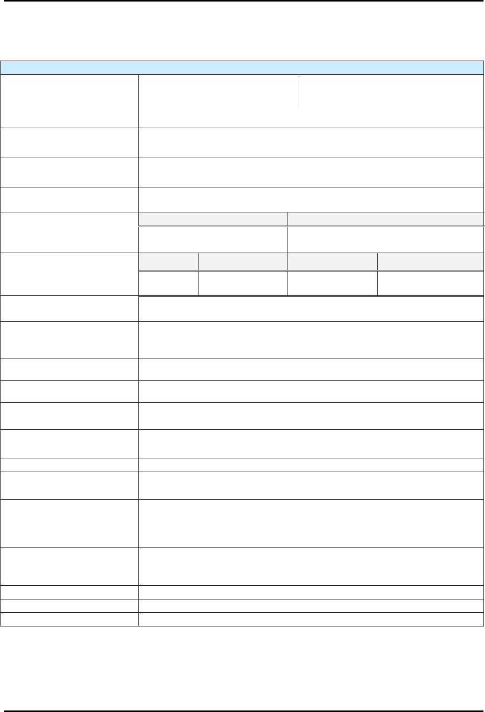
The dispensing system facility requirements, specifications, and stability analysis are listed in Table 9-1.
All facility power sources must be safely grounded. These specifications are intended as a convenient
reference for installation, system relocation, planning and operation. Meeting the requirements will ensure
reliable operation and safety of the dispensing system.
WARNING! To ensure optimal performance and safety, it is necessary to install the
dispensing system in a facility that meets the requirements listed in Table 9-1. If
you have any questions, please contact Asymtek Technical Support.
S2-9XXX Series Dispensing System IOM Manual Specifications
9-2 © 2023 Nordson Corporation
9.2 Facility Requirements
Table 9-1 Specifications
Facilities Requirements – All Models
System Footprint
Single station (width x depth):
Two stations (width x depth):
Three stations (width x depth):
600 x 1321 mm (23.6 x 52.0 in.)
850 x 1321 mm (33.5 x 52.0 in.)
1100 x 1321 mm (43.3 x 52.0 in.)
See 9.4 System Dimensions for system drawings.
Clearance Space
Requirement
915 mm
Power (Mains)
Adaptive power supply that accommodates supply voltages between
200-240 VAC, 47-63 Hz single phase.
Short Circuit Current Rating
(SCCR)
5 KA
Facility Circuit Requirement
1
S2-9XXX w/ 10A Power Supply
S2-9XXP or S2-9XXX w/ 30A Supply
10A
30A
(NEMA L6-30 Outlet Plug Provided)
Amperage (typical
Single lane Dual lane Per Heated Tool Total Amperage
4.6A 5.2A 4.7A
Base system +
heated tooling
Installation
(Over-Voltage Category)
Category II
Air Supply
2
Two air supplies: one with 3 CFM @ 100 psi for contact tooling, a second one
with 1 CFM @ 100 psi for the rest of the system (100 psi = 689 kPa, 6.8 atm).
Pneumatic Fittings 9084-23-14, 1/4-inch quick disconnect fittings
Air Consumption Application-dependent
House Vacuum (S2-9XXC) ~1 CFM @ 22 inHg max during purge routine
Energy Consumption
~6.0KWh max (with heat)
~0.4KWh max (without heat)
System Noise
<70 dBA, 76 db peak @ 1 M (does not include valve operation noise)
Environmental Conditions
(Operation and Storage)
Shipping: 5-55 °C, 5-90% RH
Operating: 18-28
°
C, 5-90% RH
Ventilation
Downdraft or updraft
Vent port diameter: 147.6 mm (5.8 in.)
NOTE: Contact the factory regarding impingement heat applications:
100 cfm from the exhaust port may be required.
System Weight
3
Single station:
Two stations:
Three stations:
377 kg. (31 lbs)
399 kg. (880 lbs)
422 kg. (930 lbs)
Crate Dimensions
1930 x 1321 x 1981 mm (76.0 x 52.0 x 78.0 in.)
Crated Weight
590 kg (1300 lbs)
Standards Compliance
SMEMA, CE, SEMI-S2, SEMI-S8, NFPA 79
1
10A power manager may use either 120VAC or 240VAC input power supply
2
S2-9XXX/9XXP system when configured with regular impingement tools: requires one air supply with 9 CFM @ 100 psi for
impingement air and a second air supply with 1 CFM @ 100 psi for the rest of the system. S2-9XXX/900P system when configured
with the high-flow impingement option requires one air supply with 14 CFM @ 100 psi for impingement air and a second air supply
with 1 CFM @ 100 psi for the rest of the system.
3
Basic weight without options; actual system weight will depend on the specific configuration.