Spectrum+Operating+Manual.pdf - 第92页
S2-9 XX X Se ri es Disp ensi n g Syst em IOM Man ual Calibration and Adjus tment 5-16 © 2023 Nordson Corporatio n NOTE If the fluid pressure do es re gister on the digital gau ge, you mus t man ually enable the flui d …
S2-9XXX Series Dispensing System IOM Manual Calibration and Adjustment
© 2023 Nordson Corporation 5-15
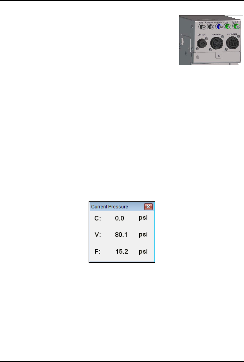
4. Connect the external pressure gauge to the desired connection
(valve, fluid, or cooling) on the dispensing system bulkhead
(Figure 5-16) using a quick disconnect fitting.
For the valve pressure reading, insert the external pressure
gauge hose into the black Valve 1 Off connection on the
bulkhead. If there is no reading, connect the hose to the
blue Valve 1 ON connection.
You should now have a reading at the digital gauge.
5. Compare the external gauge pressure reading to the set point
displayed on the Air Pressure tab (Figure 5-15).
Figure 5-16 Dispensing
System Bulkhead
6. If the pressure reading on the external pressure gauge does not match the software set
point, click on the value in the "Set Point Offset" column and enter the difference between
the actual output (reading on the external gauge) and the set point on the Air Pressure tab.
Click on
Apply. A positive value will increase the output, and negative value will lower
the output. For example, if the gauge reading is 80.2 and the software set point is 80.0,
enter -0.2 in the “Set Point Offset” column. The external gauge output should now be 80.0.
After the set point has been calibrated, it is necessary to calibrate the external pressure
gauge to the software reading.
To calibrate the Fluidmove current pressure reading to the external gauge reading:
1. Press [Ctrl + P] on the dispensing system keyboard to open the Current Pressure window
(Figure 5-17).
The current pressure is the same as the pressure shown in the “Reading” column on the
Air Pressure tab in the Local Machine Offsets window (Figure 5-15).
Figure 5-17 Current Pressure Window
2. If the reading on the external gauge does not match the current pressure reading in the
software, click on the value in the “Reading Offset” column (Figure 5-15) and enter the
difference between the actual output (reading on the digital gauge) and the reading on the
Air Pressure tab. Click on
Apply.
A positive value will increase the reading, and negative value will lower the reading.
For example, if the gauge reading is 80.0 and the software reading is 75.0, enter 5.0 in
the Reading Offset column. The software reading will change to 80.0.
3. When all applicable outputs have been calibrated, click
OK in the Local Machine Offsets
Window. The values are now set and the E/P controllers are calibrated.
S2-9XXX Series Dispensing System IOM Manual Calibration and Adjustment
5-16 © 2023 Nordson Corporation
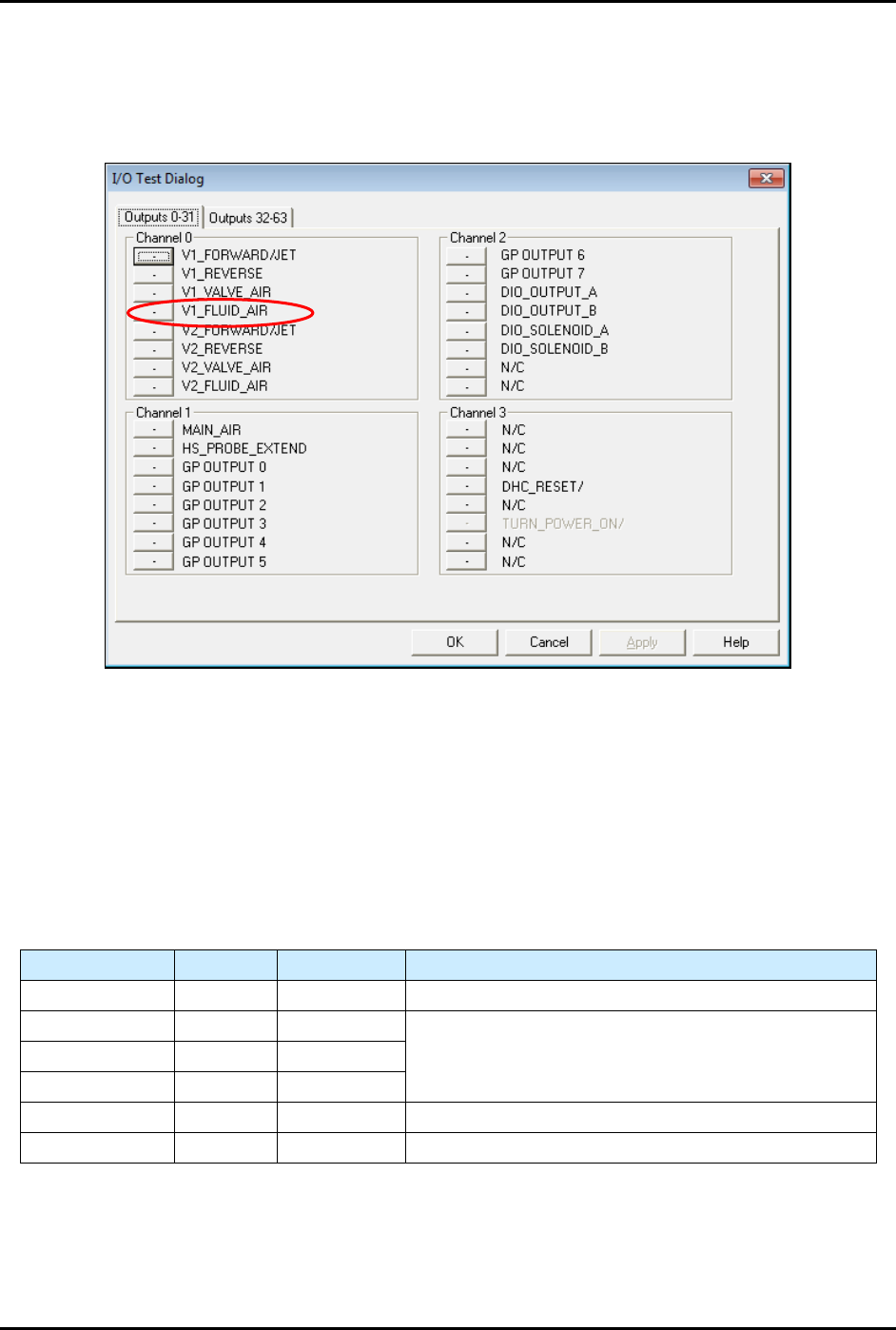
NOTE If the fluid pressure does register on the digital gauge, you must manually
enable the fluid pressure output by selecting
Tools>Dispenser from the
Fluidmove Main Window and toggling the Valve 1 Fluid Air (V1_Fluid_Air)
(Figure 5-18).
Figure 5-18 I/O Test Dialog
5.10 Adjusting the Air Pressure
5.10.1 Air Regulators and Gauges
Air pressure is set manually at the regulator or in the Fluidmove software if the E/P (electronically controlled
pneumatic) regulators option is installed.
Refer to the Fluidmove User Guide or Fluidmove Online Help for
instructions on using the E/P option.
Table 5-2 Manual or E/P Option
Air Pressure Manual E/P Option
Main Air Yes No See 3.13 Adjusting the Main Air Pressure.
Coax/Cooling Yes Yes
See 5.10.3 Adjusting the Cooling/Coaxial, Valve, and
Fluid Air Pressure.
Valve Air Yes Yes
Fluid Air Yes Yes
Lift Table Yes No See 5.10.2 Adjusting the Tooling Air Pressure.
Heater Yes No See 5.14 Calibrating the Heaters.
S2-9XXX Series Dispensing System IOM Manual Calibration and Adjustment
© 2023 Nordson Corporation 5-17
5.10.2 Adjusting the Tooling Air Pressure
The tooling air pressure regulates air supplied to the stop pins and lift tables. The regulator receives air
from the main air regulator located on the back of the dispensing system.
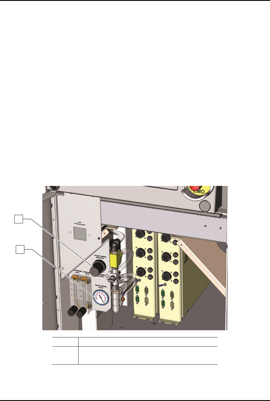
To adjust the tooling air pressure (Figure 5-19):
1. Locate the tooling air pressure regulator adjustment knob in the front cabinet.
2. Rotate the adjustment knob counterclockwise until the gauge registers 0 psi.
3. Rotate the adjustment knob clockwise until the associated gauge registers the air pressure
value (kPa or psi) required by your dispensing application.
For accurate pressure adjustment, lower the pressure below the desired level and then
increase to the desired pressure.
NOTE Pressure settings depend on the fluid being dispensed and dispensing valve
being used. Refer to the applicable dispensing valve manual for additional
information.
4. Monitor the tooling pressure gauge to make sure that pressure builds at a steady rate. A drop
in air pressure can indicate an air leak.
If there is an air leak, identify the source, shut off the facility air, and fix the leak before
proceeding.
Item
Description
1 Tooling Pressure Regulator
2
Tooling Pressure Gauge
Figure 5-19 Adjusting the Tooling Pressure Regulator
1
2