Spectrum+Operating+Manual.pdf - 第45页
S2-9 XXX Se ri es Dispensing Sys te m IOM Man ual Safety © 2023 Nordson Co rporat ion 2-13 2.11 Residual Safety Ri sk s Safety Hazard Risk A rea A hand crush or pinch point hazard is created by the m ovement of the con v…
S2-9XXX Series Dispensing System IOM Manual Safety
2-12 © 2023 Nordson Corporation
Item
Description
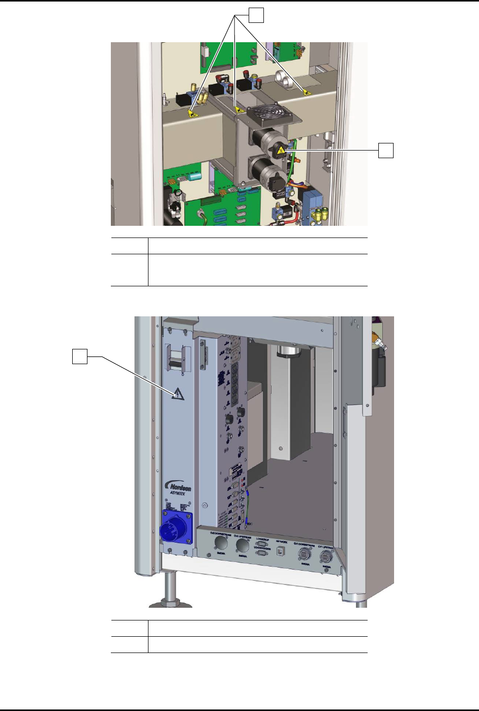
1 Hand Entanglement Label
2 Hot Surface Label
Figure 2-7 Safety Warning Labels - Rear Cabinet
Item Description
1 Electrical Warning Label
Figure 2-8 Safety Warning Labels - Power Manager
1
1
2
S2-9XXX Series Dispensing System IOM Manual Safety
© 2023 Nordson Corporation 2-13
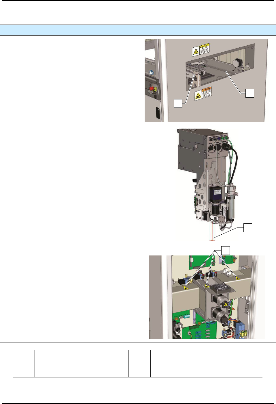
2.11 Residual Safety Risks
Safety Hazard
Risk Area
A hand crush or pinch point hazard is created by
the movement of the conveyor. DO NOT reach into
the conveyor while the system is operating. Keep
hands away from this area unless the system power
is off.
A high risk burn hazard is created by the heaters.
Keep hands away from this area unless the system
power is off and heaters have cooled.
If the system is equipped with a Class 2 laser height
sensor, serious eye injury may occur by staring
directly into the laser beam on the laser height
sensor. The laser height sensor is located behind
the camera and not visible from the front of the
machine. DO NOT bypass the safety interlock. DO
NOT open the dispensing area door while the laser
is on. Wear protective goggles when using the laser
height sensor, see 2.8 Laser Radiation.
A hand entanglement hazard is created by the
movement of the drive cables and motor pulley.
DO NOT remove the access panels while the
system is operating. DO NOT bypass the safety
interlock. DO NOT operate the equipment with the
access panels removed and/or doors open. Keep
hands away from this area unless the system power
is off.
Item
Description
Item
Description
1
Conveyor
3
Laser Beam
3
Heaters
4 Drive Cables and Motor Pulley
Figure 2-9 S2-9XXX Safety Hazard Areas
1
2
4
3
S2-9XXX Series Dispensing System IOM Manual Safety
2-14 © 2023 Nordson Corporation
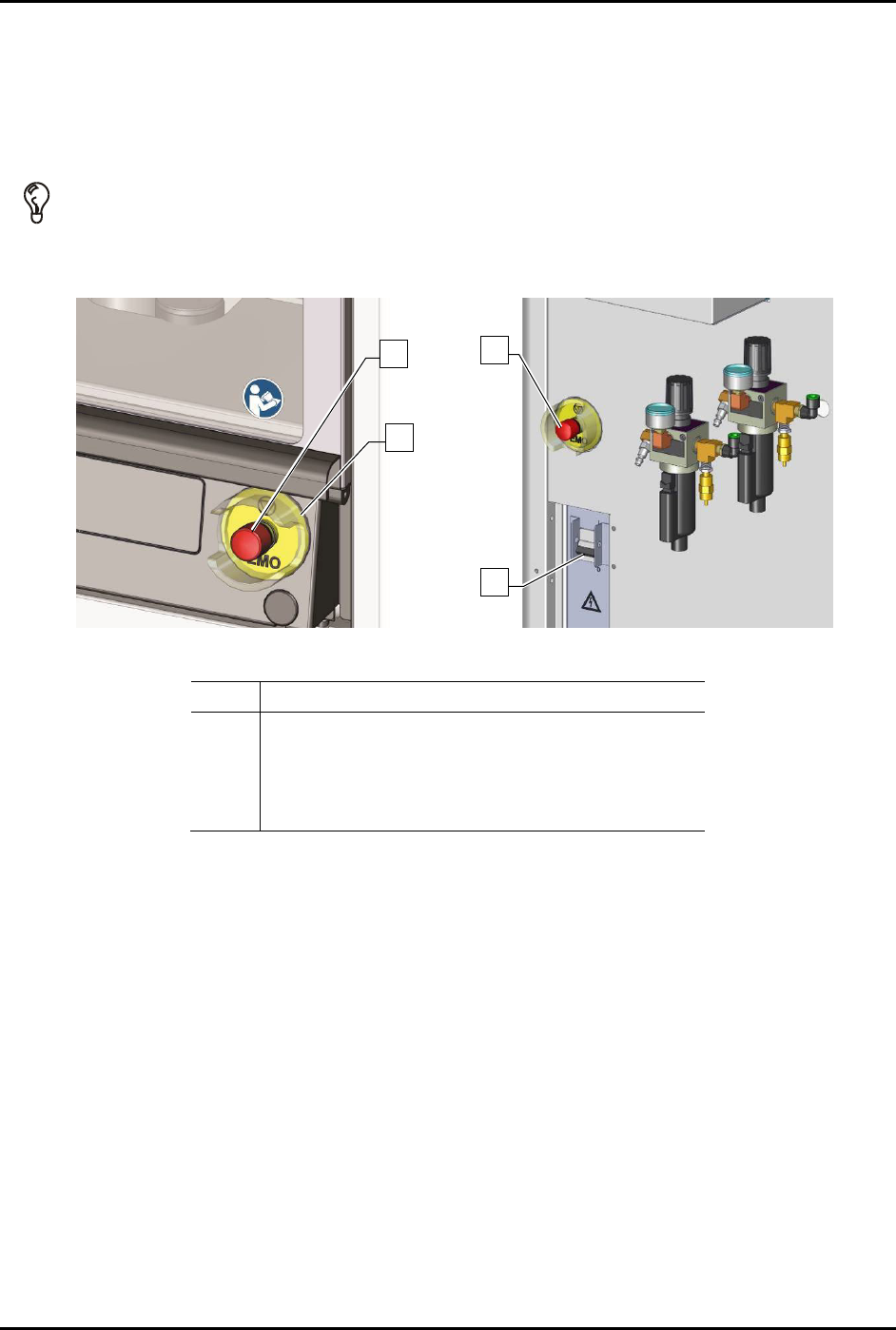
2.12 Emergency Shutdown
In the event of an emergency or malfunction, press the EMO button. The dispensing system has two EMO
buttons. The EMO buttons are the large red buttons located on the front panel and the rear of the
dispensing system (Figure 2-10). Activating the EMO vents all pressure in the pneumatic system and cuts
power to all components except the laptop computer, the camera, the interior light, and the light beacon.
TIP If the operator or technician is unable to reach the EMO button, the main circuit breaker ,
which is located on the back of the system, can be used for emergency shutdown
(Figure 2-10).
Front Panel Rear View
Item
Description
1 Rear EMO button
2 Front EMO button
3 EMO Guard
4 Main Circuit Breaker
Figure 2-10 EMO/Main Circuit Breaker Locations
2
3
1
4