Spectrum+Operating+Manual.pdf - 第119页
S2-9 XXX Se ri es Dispensing Sys te m IOM Man ual Maintenance © 2023 Nordson C orporatio n 6-7 6.6 Draining the Water Tr ap T he facility air supply may c ontain moisture th at can damage the disp ensing system, t he dis…
S2-9XXX Series Dispensing System IOM Manual Maintenance
6-6 © 2023 Nordson Corporation
6.5.2 Replacing the Purge Boot
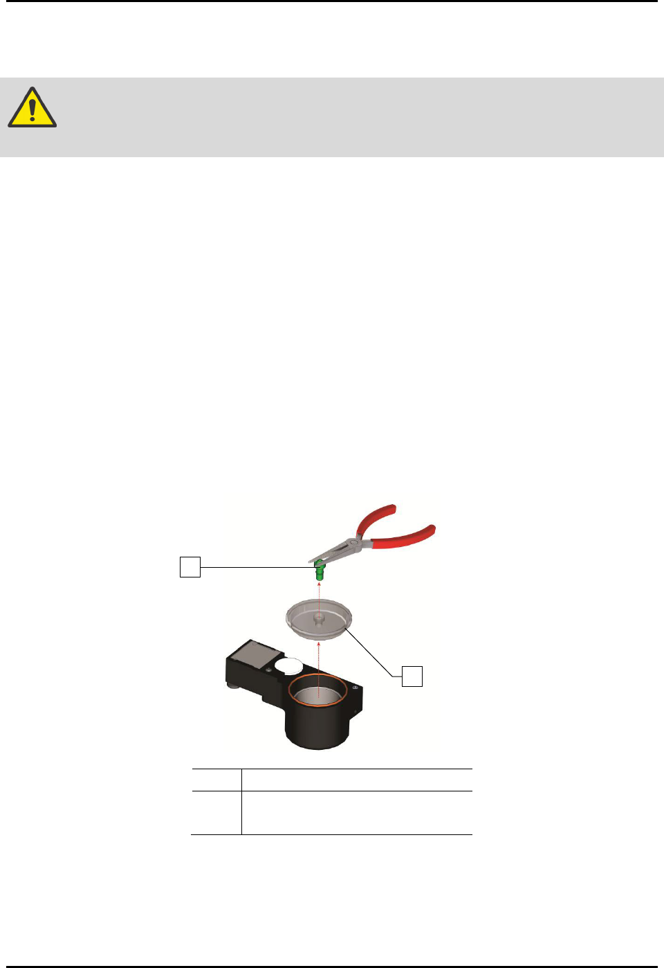
To replace the purge boot (Figure 6-2):
WARNING! Follow all manufacturer SDS, facility requirements, and local ordinances
concerning personal protective equipment and disposal of hazardous materials.
1. When the dispensing system is idle, open the dispensing area door.
2. Remove the purge station cover.
3. Discard the used purge boot in accordance with local safety/environmental regulations.
4. If the purge station cover is dirty, clean it with the recommended cleaning agent and a soft
cloth.
5. Insert a new purge boot, narrow end first, into the top of the purge station cover.
6. Push the purge boot downward through the hole in the cover until it starts to emerge from
the bottom.
7. Using fingers or needle-nose pliers, grip the bottom of the purge boot and pull gently
through the hole until it is fully seated. Slight scoring on the bottom end of the purge boot is
acceptable, but the top of the purge boot must be undamaged.
8. Reinstall the purge station cover.
9. Close the dispensing area door.
Item
Description
1
Purge Boot
2 Purge Station Cover
Figure 6-2 Replacing the Purge Boot
2
1
S2-9XXX Series Dispensing System IOM Manual Maintenance
© 2023 Nordson Corporation 6-7
6.6 Draining the Water Trap
The facility air supply may contain moisture that can damage the dispensing system, the dispensing
system is equipped with two water traps that condense this moisture before it enters the pneumatic
system. The operator or technician must drain the water trap weekly or whenever it is full.
Tools and Materials Needed:
• Container for wastewater
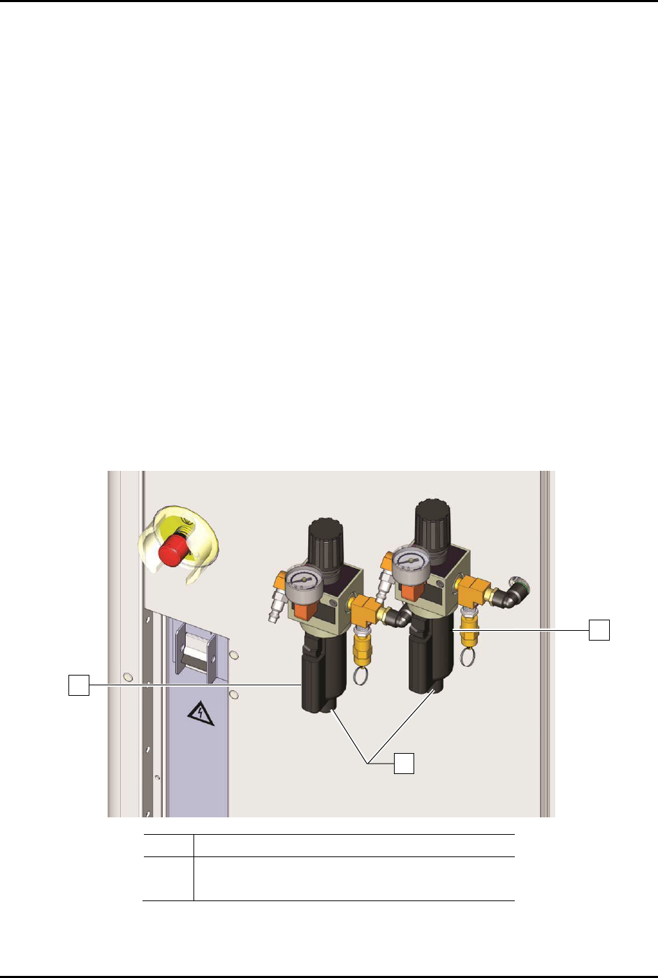
To drain the water traps (Figure 6-3):
NOTE The following procedure is for the water traps at the rear of the dispensing system. If the
system water traps are connected to a bulk reservoir, the bulk reservoir should be drained
as needed.
1. Locate the water traps at the rear of the system.
2. Shut off facility air pressure and disconnect the facility air supply from the main air
pressure regulator inlet.
3. Hold a container under the water traps to catch the water and open the water drain knob by
turning counterclockwise.
4. After the trap has been drained, close the water trap drain knob by turning clockwise.
5. Reconnect the facility air supply to the main air pressure regulator inlet.
Item
Description
1 Water Trap
2 Drain Knobs
Figure 6-3 Draining the Water Traps
1
2
1
S2-9XXX Series Dispensing System IOM Manual Maintenance
6-8 © 2023 Nordson Corporation
6.7 Verifying Interlock Functionality
To verify interlock functionality:
1. Power on the dispensing system, see 4.3 Powering on the Dispensing System.
2. Start Fluidmove. Refer to the Fluidmove User Guide or Fluidmove Online Help.
3. Open the Fluidmove Jog window and use the position controls to move the dispensing head
in the X, Y, and Z-axes.
4. Open the dispensing area door.
Confirm that the light beacon is yellow and that there is a Fluidmove message
indicating that the dispensing area door is open.
5. Manually move the dispensing head in the X, Y, and Z-axes.
Confirm that the dispensing head moves freely (motors are not producing force).
6. While observing the dispensing head, close the dispensing area door and acknowledge the
Fluidmove error message.
Confirm that the dispensing head moves to the position it was in prior to opening the
dispensing area door.
WARNING! Immediately remove the dispensing system from service if the light beacon is not
yellow or the dispensing head does not move freely when the dispensing area
door is open.