Spectrum+Operating+Manual.pdf - 第31页
S2-9 XXX Se ri es Dispensing Sys te m IOM Man ual Introductio n © 2023 Nordson Co rporat ion 1-21 1.9.9 Rea r Cabinet I tem Name Description 1 Convey or/H eater Module (systems with heat ) Controls all conve yor function…
S2-9XXX Series Dispensing System IOM Manual Introduction
1-20 © 2023 Nordson Corporation
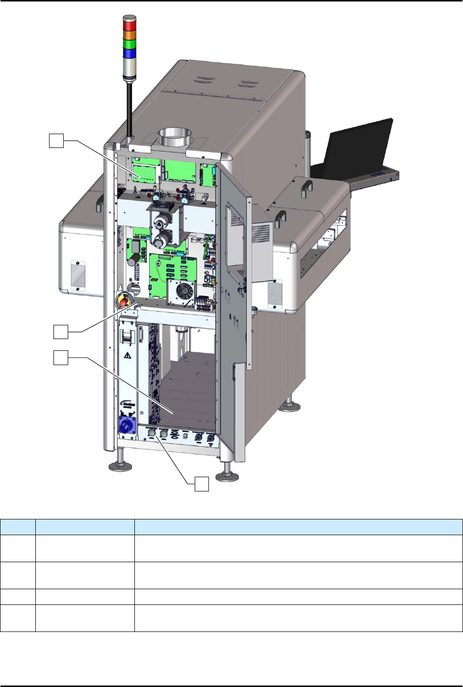
Figure 1-14B Rear View Open (S2-9XXP with Pre-Queue and Post-Queue Stations)
Item
Name
Description
1 Upper E-Pan
The Upper E-Pan houses the dispense head controller, Z-axis servo amp,
and applicator pneumatics.
2 Lower E-Pan
The Lower E-Pan houses the main PWA, X-Y axis servo amps, main air
pneumatic valves, and conveyor pneumatic valves.
3
Rear Cabinet
See 1.11.9 Rear Cabinet.
4
Rear Panel
Connections
See 1.11.10 Rear Panel Connections.
Figure 1-15 Rear View Open
1
3
4
2
S2-9XXX Series Dispensing System IOM Manual Introduction
© 2023 Nordson Corporation 1-21
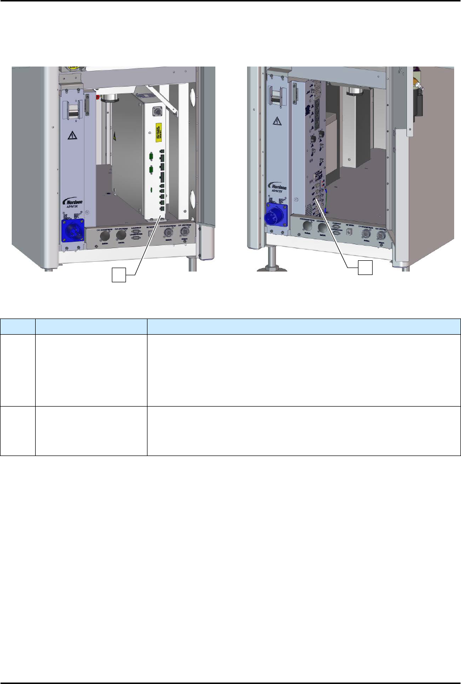
1.9.9 Rear Cabinet
Item
Name
Description
1
Conveyor/Heater
Module
(systems with heat)
Controls all conveyor functions (motors, sensors, pneumatics, etc.). It
receives power from the power manager and supplies AC power to the
substrate heaters in the dispensing area. If your system is equipped
with dual conveyors, there will be two Conveyor/Heater Modules. Note:
if the system does not have heat, it will have a conveyor controller
instead of a Conveyor/Heater Module.
2
Power Manager
(30A shown)
The Power Manager is located inside the rear cabinet. It houses the
main circuit breaker and the main power inlet. It also contains the EMO
circuitry. The EMO buttons, the green ON (I) button, and the black
OFF
(
0
) button are directly connected to the Power Manager.
Figure 1-16 Rear Cabinet
2
1
S2-9XXX Series Dispensing System IOM Manual Introduction
1-22 © 2023 Nordson Corporation
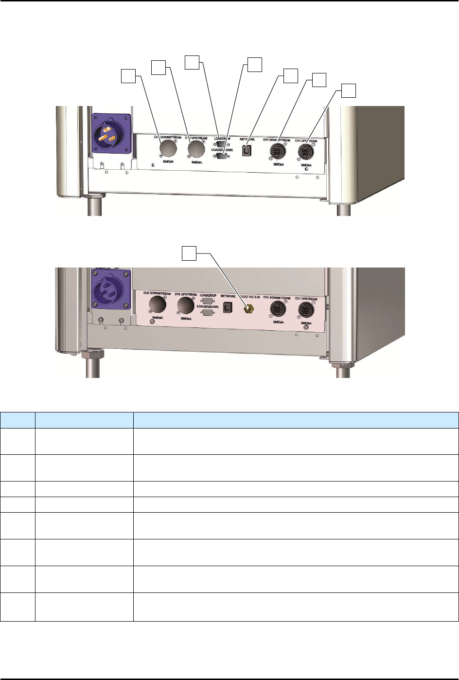
1.9.10 Rear Panel Connections
S2-9XXX/S2-9XXP
S2-9XXC
Item
Name
Description
1 CV2 Downstream
Allows for SMEMA communication between Conveyor 2 and a
downstream machine such as an unloader.
2 CV2 Upstream
Allows for SMEMA communication between Conveyor 2 and an upstream
machine such as a loader.
3 Loader/Up Not used on this machine.
4 Loader/Down Not used on this machine.
5 Network
Allows the dispensing system to communicate with a host computer on a
local area network. Necessary for SECS/GEM functionality.
6 CV1 Downstream
Allows for SMEMA communication between Conveyor 1 and a
downstream machine such as an unloader.
7 CV1 Upstream
Allows for SMEMA communication between Conveyor 1 and an upstream
machine such as a loader.
8
House Vacuum
(S2-9XXC only)
The House Vacuum connection is required for valve purge and to hold
workpieces to the tooling on the cleanroom system.
Figure 1-17 Rear Panel Connections
NOTE CV2 connectors are only present on dual conveyor dispensing systems.
1
2
3
4
5
6
7
8