Spectrum+Operating+Manual.pdf - 第131页
S2-9 XXX Se ri es Dispensing Sys te m IOM Man ual Maintenance © 2023 Nordson C orporatio n 6-19 6.11.2 Tensioning the Z Cable To tension the Z cable (Fig ure 6 - 12 ): 1. P erform a serv ice shutd own , see 2.14 Service …
S2-9XXX Series Dispensing System IOM Manual Maintenance
6-18 © 2023 Nordson Corporation
6.11 Tensioning the Cables
Periodic tensioning of the dispensing system mechanical drive cables can prevent premature failure of the
cables. For dispensing system operating in a 24/7 production environment, tension the mechanical drive
cables approximately every six months. For systems operating in a single-shift environment (eight hours a
day or less), this should be done once a year.
Tools and Materials Needed:
• Hex Wrench Set
WARNING! This procedure should only be performed by a trained service technician.
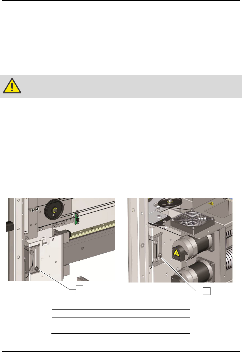
6.11.1 Tensioning the X/Y Cables
To tension the X/Y cables (Figure 6-11):
1. Perform a service shutdown, see 2.14 Service Shutdown.
2. Open the dispensing area door.
3. Loosen the X-axis and two (2) Y-axis tensioner screws.
4. Manually move the Z-head in a circle around the entire length and width of the dispensing
area approximately five (5) times.
5. Stop in the center of the dispensing area.
6. Retighten the tensioner screws.
Figure 6-11A Tensioning the X-Axis Cables
Figure 6-11B Tensioning the Y-Axis Cables
Item
Description
1 X-Axis Tensioner Screw
2 Y-Axis Tensioner Screw (only 1 shown)
Figure 6-11 Tensioning the Cables
2
1
S2-9XXX Series Dispensing System IOM Manual Maintenance
© 2023 Nordson Corporation 6-19
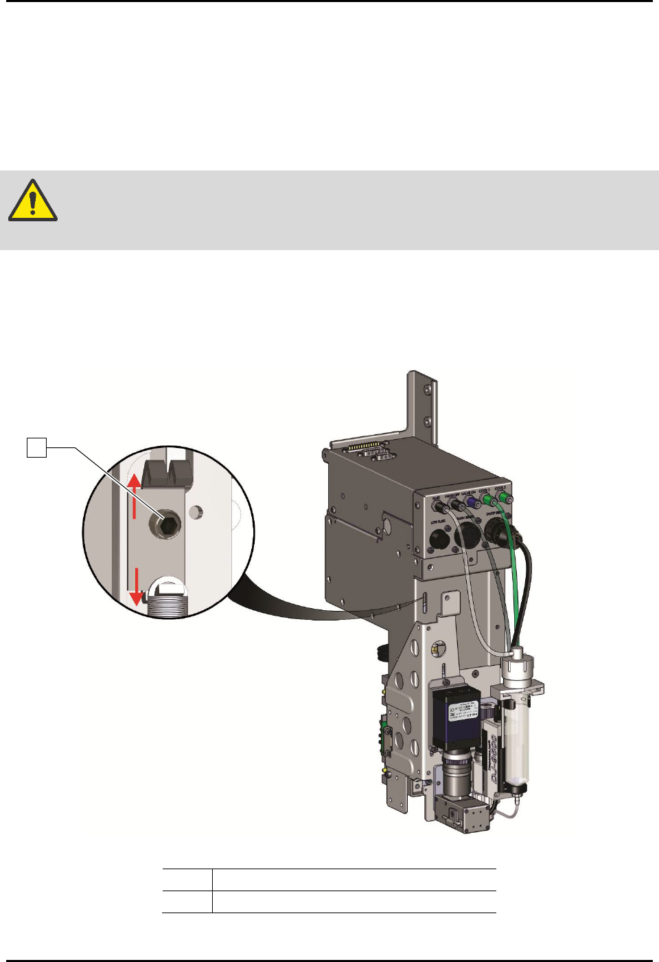
6.11.2 Tensioning the Z Cable
To tension the Z cable (Figure 6-12):
1. Perform a service shutdown, see 2.14 Service Shutdown.
2. Open the dispensing area door.
3. Use an M3 hex key to loosen (one turn) the tensioner screw.
WARNING! DO NOT remove the tensioner screw. If removed, the entire Z-head must be
disassembled.
4. Manually move the dispensing head up and down the full length of the axis. Repeat
three (3) to five (5) times.
5. Tighten the tensioner screw.
6. Close the dispensing area door.
Item
Description
1
Tensioner Screw
Figure 6-12 Tensioning the Z-Axis Cables
1
S2-9XXX Series Dispensing System IOM Manual Maintenance
6-20 © 2023 Nordson Corporation
6.12 Adjusting the Linear Encoders
Tools and Materials Needed:
• 0.8 mm Gauge (included with linear encoder)
• Thread Locker
•
3 mm Hex Key
• Torque Wrench 0-100 in-lbs
6.12.1 Adjusting the X-Axis Linear Encoder
To adjust the X-axis linear encoder
1. If necessary, power on the dispensing system, see 4.3 Powering on the Dispensing System.
2. Exit Fluidmove.
3. Open the dispensing area door.
4. Verify that the light beacon is yellow and that all axes move freely by hand.
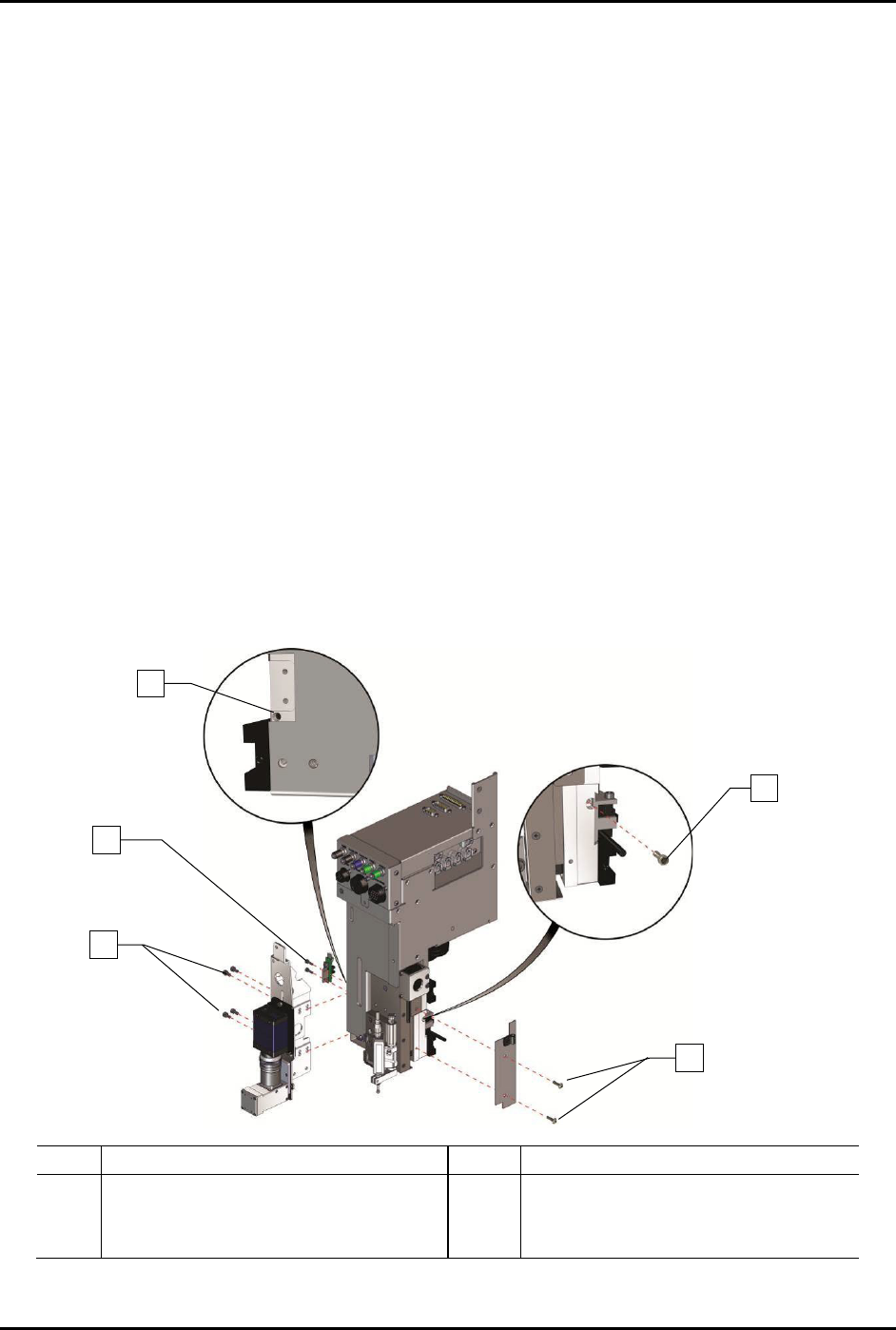
5. To gain access to the X-axis linear encoder (Figure 6-13):
a. Use a 3 mm hex key to remove the four (4) screws on the camera bracket, two (2)
Z-head home switch screws, and two (2) Z-head panel screws.
b. Remove one (1) encoder mounting bracket screw securing the encoder mounting
bracket to the Z-head.
In order to remove the encoder mounting bracket screw, you will need to install and
tighten one (1) M4 setscrew on the left of the Z-head below the on-switch.
Item
Description
Item
Description
1
M-4 Setscrew
4
Encoder Mounting Bracket Screw
2
Z-Head Home Switch Screws (2)
5
Z-Head Panel Screws (2)
3
Camera Bracket Screws (4)
Figure 6-13 Accessing the Linear Encoder
1
3
4
5
2