Spectrum+Operating+Manual.pdf - 第80页
S2-9 XX X Se ri es Disp ensi n g Syst em IOM Man ual Calibration and Adjus tment 5-4 © 2023 Nordson Corporatio n 9. For fine focus usin g the lens focus adjustmen t , pe rform the following st eps: a. Loosen the lo cking…
S2-9XXX Series Dispensing System IOM Manual Calibration and Adjustment
© 2023 Nordson Corporation 5-3
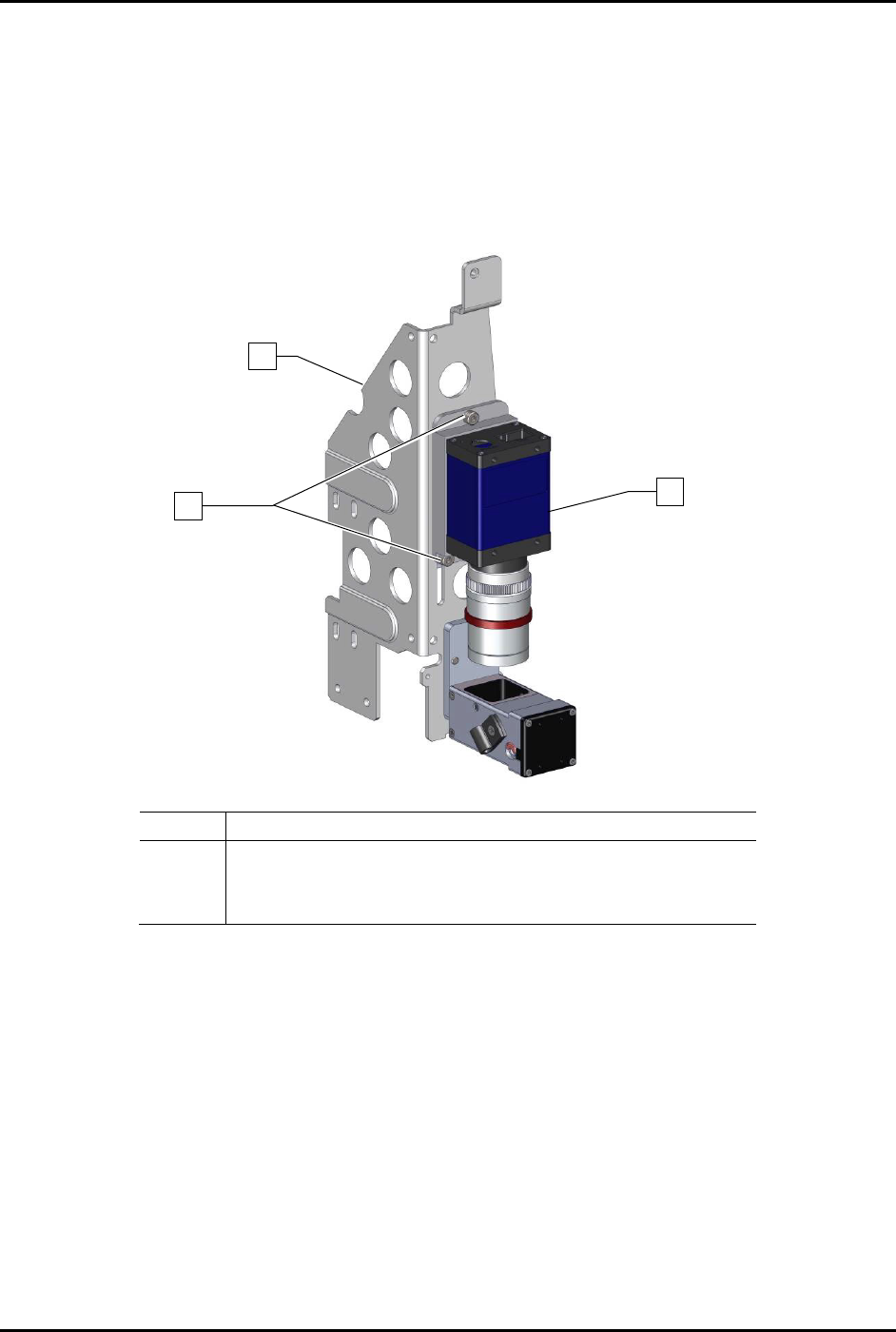
8. For rough focus, perform the following steps:
a. Hold the camera and use a 3 mm hex key to loosen the three (3) screws securing the
camera to the bracket (Figure 5-2).
b. Slowly move the camera up and down in the bracket.
c. When a sharp image is obtained in the Video Window, hold the camera and tighten the
three (3) screws securing the camera to the bracket using a 3 mm hex key.
Item
Description
1
Bracket
2
Screw (Third screw is located opposite of lower left screw)
3
Camera (Item 55)
Figure 5-2 Rough Focus
1
3
x3
2
S2-9XXX Series Dispensing System IOM Manual Calibration and Adjustment
5-4 © 2023 Nordson Corporation
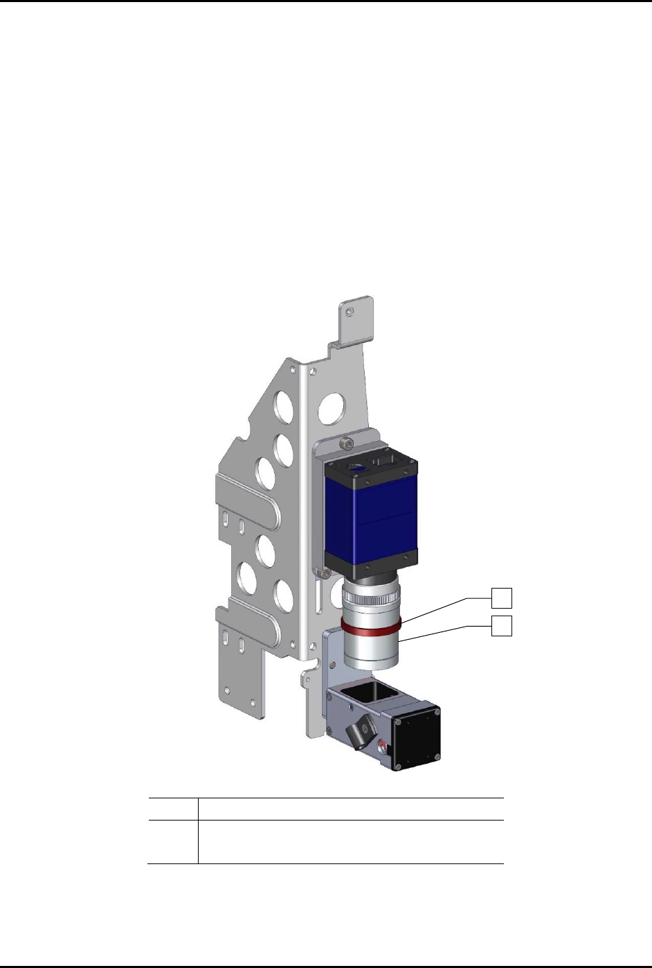
9. For fine focus using the lens focus adjustment, perform the following steps:
a. Loosen the locking ring on the camera lens.
b. Turn the middle section of the camera lens, clockwise or counterclockwise, until a
sharp image is obtained in the Video Window.
c. Tighten the locking ring to lock the focus.
10. Perform camera calibration, see 5.5 Calibrating the Camera.
11. Adjust the lighting and color levels.
Refer to the Fluidmove User Guide or Fluidmove
Online Help
for adjusting the lighting and color levels.
12. Perform machine offset procedures.
Refer to the Fluidmove User Guide or Fluidmove
Online Help
to perform the offset procedures.
Item Description
1 Locking Ring
2 Middle Section
Figure 5-3 Additional Adjustments
1
2
S2-9XXX Series Dispensing System IOM Manual Calibration and Adjustment
© 2023 Nordson Corporation 5-5
5.5 Calibrating the Camera
NOTE This procedure assumes the dispensing system has been powered on, Fluidmove is
running, a substrate is available, and the camera has been focused. The camera is self-
calibrating when using the calibrate button from the Setup Vision window. The software
compares the pixel count to machine units by moving away from the taught image by a
known value, finding the image again, and assigning a pixel-count-to-machine-unit value.
With this value established, the vision system can accurately find the substrate and
dispense at the correct location (provided the vision target image is within the field of
view).
NOTE If the camera is ever refocused to accommodate a different part height, the calibration
routine MUST be run again.
To calibrate the camera:
1. In the Fluidmove Programming Window, click the
Load a Board icon.
The conveyor will transport the substrate to the dispense station and the lift mechanism
will lift it off the conveyor belt.
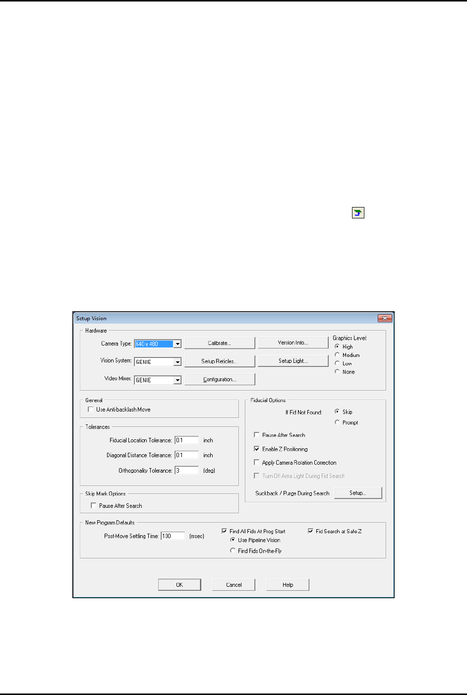
2. In the Fluidmove Main Window, click on
Configuration > Setup Vision.
The Setup Vision window opens (Figure 5-4).
Figure 5-4 Setup Vision