Spectrum+Operating+Manual.pdf - 第145页
S2-9 XXX Se ri es Dispensing Sys te m IOM Man ual Troubleshootin g © 2023 Nordson C orpor ation 7-7 7.4.8 Pn eumatic Tab le 7-8 Pneu ma t ic Trouble sho oting S ymptom Po ssible C ause Recovery No air pressur e Failed ma…
S2-9XXX Series Dispensing System IOM Manual Troubleshooting
7-6 © 2023 Nordson Corporation
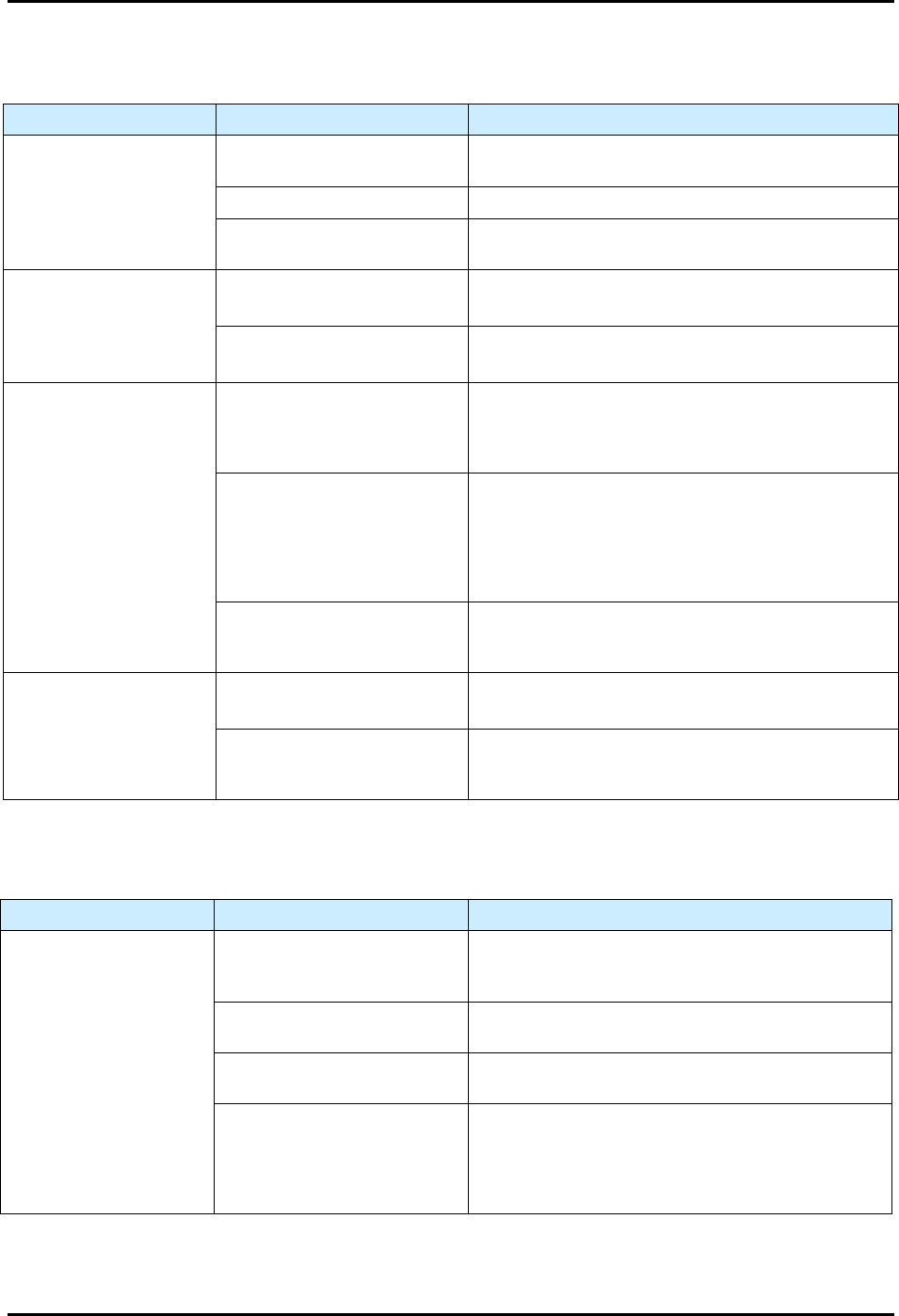
7.4.6 Mechanical/Tactile Height Sensor
Table 7-6 Height Sensor Troubleshooting
Symptom Possible Cause Recovery
Probe does not drop or
retract
Probe is damaged.
Check for bent probe. Replace if necessary, see 8.10.2
Replacing the Mechanical/Tactile Height Sensor Probe.
No air pressure. Verify main air pressure is ON (I).
Pneumatic hose is kinked or
pinched.
Check pneumatic lines.
Probe either drops too
slowly or slams down with
too much force
Main air pressure not set
properly.
Readjust main air pressure regulator to system’s
nominal pressure.
Pneumatic hose is kinked or
pinched.
Check pneumatic lines.
Needle hits substrate
Probe tip is lower than the
needle tip when valve is in
dispensing position.
Adjust probe and perform “Valve Offsets” in Fluidmove,
see 5.12 Adjusting the Height Sensor Probe (Option).
Refer to the Fluidmove User Guide or Fluidmove
Online Help.
The height sensor is not set up
properly.
Test the height sensor. Fluidmove provides a height
sensor test utility from the Tools > Diagnostics
menu.
The probe can be toggled up and down to verify probe
functionality. There is also a test procedure that
captures HS trigger values. Fluidmove can display a
statistical analysis of the captured values.
HS velocity is set too high.
Reduce the HS velocity to 2 inches per second and re-
run the valve offsets. Test the height sensor from the
diagnostics menu if necessary.
Probe hits substrate
before it is fully extended
Safe Z height too low.
Reteach safe Z height. Refer to the Fluidmove User
Guide or Fluidmove Online Help.
Retract distance too low.
Reteach the retract distance in the height sensor setup.
Refer to the Fluidmove User Guide or Fluidmove
Online Help.
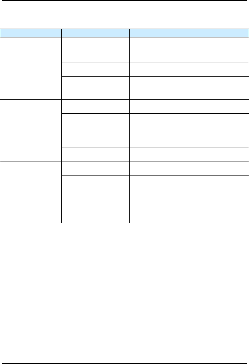
7.4.7 Needle Heater
Table 7-7 Needle Heater Troubleshooting
Symptom Possible Cause Recovery
No needle heat
Set Point (SP) value below
Present Value (PV) or the
heater is in an idle state.
Change the SP value within the Heater Controls
window. Refer to the Fluidmove User Guide or
Fluidmove Online Help.
Disconnected heater.
Verify the needle heater cable connections are
securely attached to the correct ports.
Failed DHC power.
Verify DHC indicator lights for 3.3V, -12V, and 12V
are illuminated.
Failed heater.
Verify the needle heater electrical parameters. The
resistance between pins 4 and 5 for the heating
element should be 100 ohms +/- 5 ohms. The
resistance of the RTD sensor between pins 6 and 7
should be 108 ohms, +/- 5 ohms.
S2-9XXX Series Dispensing System IOM Manual Troubleshooting
© 2023 Nordson Corporation 7-7
7.4.8 Pneumatic
Table 7-8 Pneumatic Troubleshooting
Symptom Possible Cause Recovery
No air pressure
Failed main air solenoid.
With Fluidmove initialized, go to the Tools Menu, then
IO, and toggle the command button for the main air
solenoid. The valve and fluid air buttons are also
accessible from this menu.
System not connected to
facility air supply.
Check the main air inlet at the rear of the system.
Main air regulator closed. Verify the main air regulator is set properly.
Fluidmove not started.
Fluidmove must be running to initialize the machine
pneumatics.
No fluid pressure
Air pressure setting incorrect.
Make sure the fluid pressure regulator is set to the
proper air pressure.
Incorrect bit mask.
Contact Asymtek Technical Support for correct bit
mask values that control the pneumatic states for the
particular fluid delivery system being used.
Syringe disconnected.
Connect the syringe receiver head to the fluid (silver
fitting) port on the dispensing head.
Fluidmove not started.
Start Fluidmove. Refer to the Fluidmove User Guide or
Fluidmove Online Help.
No valve pressure
Air pressure setting incorrect.
Make sure valve pressure regulator is set to the proper
air pressure.
Incorrect bit mask.
Contact Asymtek Technical Support for correct bit
mask values that control the pneumatic states for the
particular fluid delivery system being used.
Valve disconnected.
Connect the syringe receiver head to the valve (black
fitting) port on the dispensing head.
Fluidmove not started.
Start Fluidmove. Refer to the Fluidmove User Guide or
Fluidmove Online Help.
S2-9XXX Series Dispensing System IOM Manual Troubleshooting
7-8 © 2023 Nordson Corporation
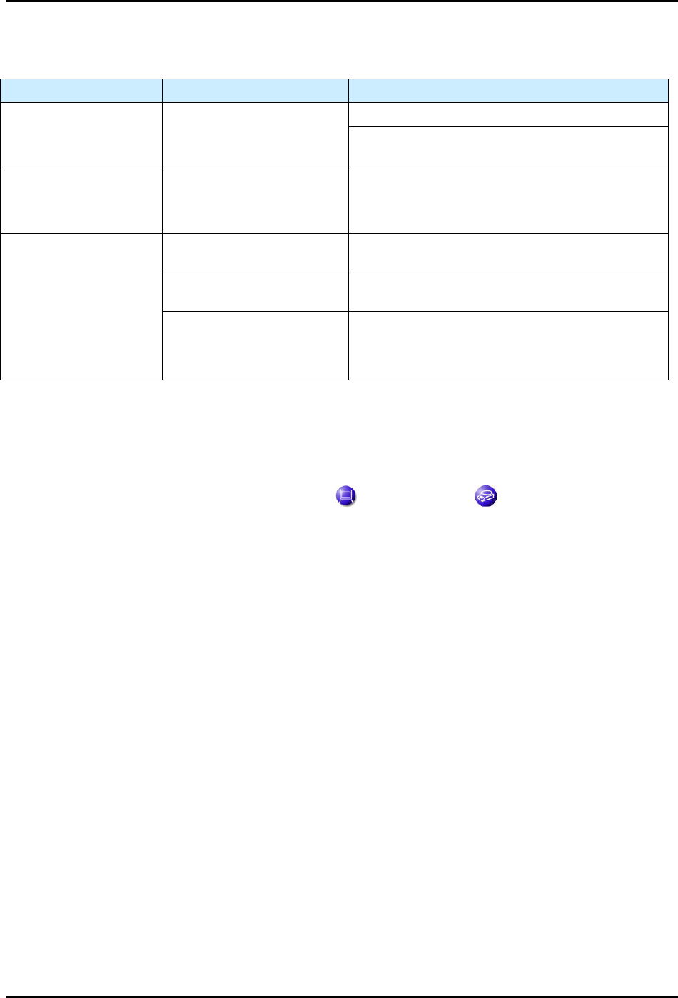
7.4.9 Scale
Table 7-9 Scale Troubleshooting
Symptom Possible Cause Recovery
No scale communication No power.
Check communication ports for proper connection.
Check power (+24V) and RS-232 communications
cables.
Scale Error No. 54
(Figure 7-2)
Pedestal not installed.
You will typically receive a Fluidmove error message
when the pedestal is not installed on the scale. There
is a minimum weight that must be placed on the
scale in order for it to read properly.
Unstable scale
Lid not on scale.
Verify that the scale lid is installed. Air turbulence will
cause scale instability issues.
Dispensing area door open.
Verify that the dispensing area door is closed. Slight
air turbulence can cause unstable readings.
Floor vibration.
In some rare cases, vibration through the floor can
cause scale instability issues. This is most common
where the dispensing system is not installed on a
concrete floor.
NOTE The scale can also be tested from the Fluidmove Terminal Mode. See instructions below.
To test the scale from the Fluidmove terminal mode:
1. In the Fluidmove Main Window, select
Tools.
2. In the Tools menu, click on
Terminal and then on Scale .
3. Use the following commands to check the scale responses:
ESC+P (escape key and capital P) Outputs the current scale value to the terminal
screen.
ESC+S (escape key and capital S) Restarts the scale but gives no response.
ESC+T (escape key and capital T) Tares and Re-zeroes the scale.
4. If the scale does not respond to those commands, then there may be a software
configuration issue. Verify the scale is configured from the configuration menu. The scale
type selected should be
SART-WZ (Figure 7-1). For detailed instructions, refer to the
Fluidmove User Guide or Fluidmove Online Help.