Spectrum+Operating+Manual.pdf - 第29页
S2-9 XXX Se ri es Dispensing Sys te m IOM Man ual Introduction © 2023 Nordson Co rporat ion 1-19 1.9.8 Rear View Open Figure 1- 13 A S2 - 9XXX Rear View Open 1 2 3 4
S2-9XXX Series Dispensing System IOM Manual Introduction
1-18 © 2023 Nordson Corporation
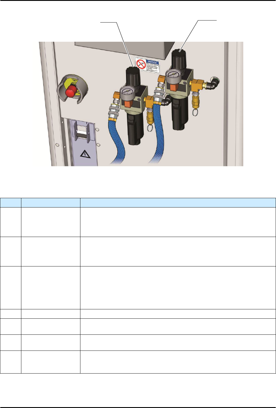
Figure 1-11B Main Air Regulator and Gauge Sets (Close-up)
Item
Name
Description
1
Main Air Regulator
and Gauge (2)
The system is equipped with two (2) Main Air Regulators and Gauges.
They control the air pressure supplied to all other system regulators. The
regulators contain built-in air filter and water traps to ensure that only
clean, dry air enters the system.
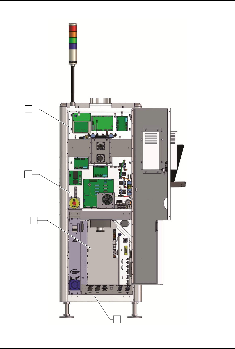
2 Rear EMO
The Rear EMO is a built-in safety feature located on the rear panel of the
dispensing system. Activating the EMO vents all pressure in the
pneumatic system, de-energizes the servo power, and cuts power to all
system components except the computer.
3 Main Circuit Breaker
The Main Circuit Breaker is the main power switch for the dispensing
system. It protects the dispensing system from facility power surges and
controls the flow of facility AC power supplied to the power manager. A
flange to the right of the Main Circuit Breaker allows it to be locked in the
OFF position during servicing. Switching OFF the Main Circuit Breaker
cuts power to all dispensing system electrical components.
4 Power Manager See 1.11.9 Rear Cabinet.
5
Main Power
Connection
The Main Power Connection connects the dispensing system to the
facility power supply via the main power cord (not shown).
6
Rear Panel
Connections
See 1.11.10 Rear Panel Connections.
7 Water Traps (2)
The facility air supply may contain moisture that can damage the
dispensing system. The Water Trap condenses this moisture before it
enters the dispenser pneumatic system.
Figure 1-12 Rear View
Fluid/Valve
Pneumatics
Conveyor/Heater
Pneumatics
S2-9XXX Series Dispensing System IOM Manual Introduction
© 2023 Nordson Corporation 1-19
1.9.8 Rear View Open
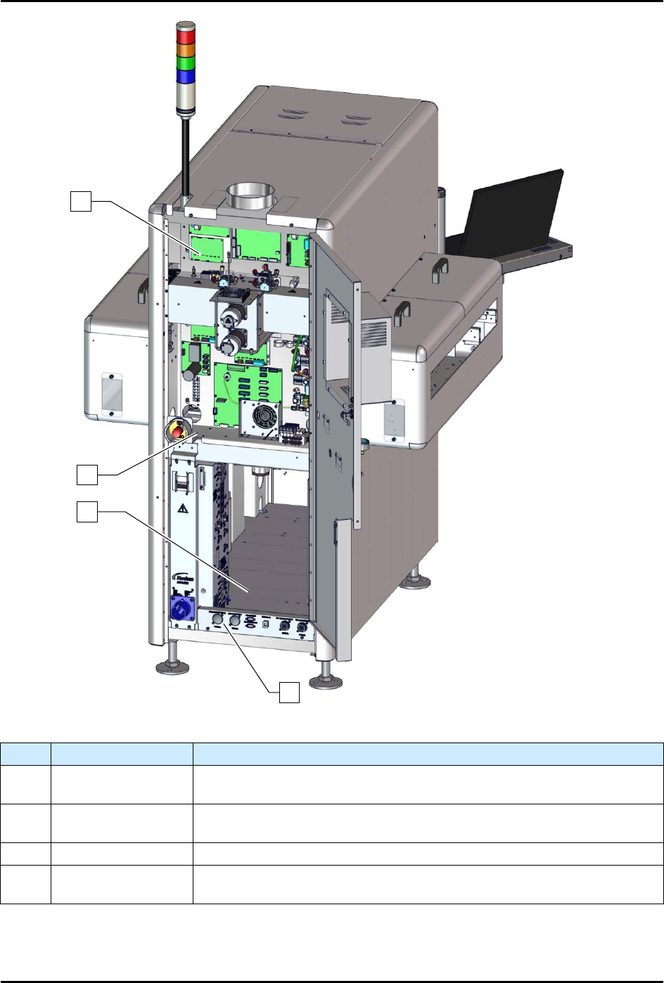
Figure 1-13A S2-9XXX Rear View Open
1
2
3
4
S2-9XXX Series Dispensing System IOM Manual Introduction
1-20 © 2023 Nordson Corporation
Figure 1-14B Rear View Open (S2-9XXP with Pre-Queue and Post-Queue Stations)
Item
Name
Description
1 Upper E-Pan
The Upper E-Pan houses the dispense head controller, Z-axis servo amp,
and applicator pneumatics.
2 Lower E-Pan
The Lower E-Pan houses the main PWA, X-Y axis servo amps, main air
pneumatic valves, and conveyor pneumatic valves.
3
Rear Cabinet
See 1.11.9 Rear Cabinet.
4
Rear Panel
Connections
See 1.11.10 Rear Panel Connections.
Figure 1-15 Rear View Open
1
3
4
2