Spectrum+Operating+Manual.pdf - 第185页
S2-9 XXX Se ri es Dispensing Sys te m IOM Man ual Parts Replacement © 2023 Nordson C orpor ation 8-33 8.16 Replacing Compon ents Inside the Lower Fro nt Door Tools and Materials Needed : • Hex Key Set (Item 59) WA RN ING…
S2-9XXX Series Dispensing System IOM Manual Parts Replacement
8-32 © 2023 Nordson Corporation
To install the off switch (Figure 8-23):
1. Install the momentary actuator in the front of the control panel.
2. Install the metal flush mount adapter and metal mounting nut onto the momentary actuator
from the rear of the control panel.
3. Apply one small drop of plastic thread locker onto the threads of the metal mounting nut.
4. Install the metal flush mount adapter and metal mounting nut from the rear of the control
panel onto the switch assembly.
5. Tighten the nut utilizing the switch mounting tool.
6. Connect the contact block to the momentary actuator.
7. Connect the power control cables to the contact block, see Table 8-3.
8. Reinstall the control panel, see 8.13.1 Removing and Installing the Control Panel.
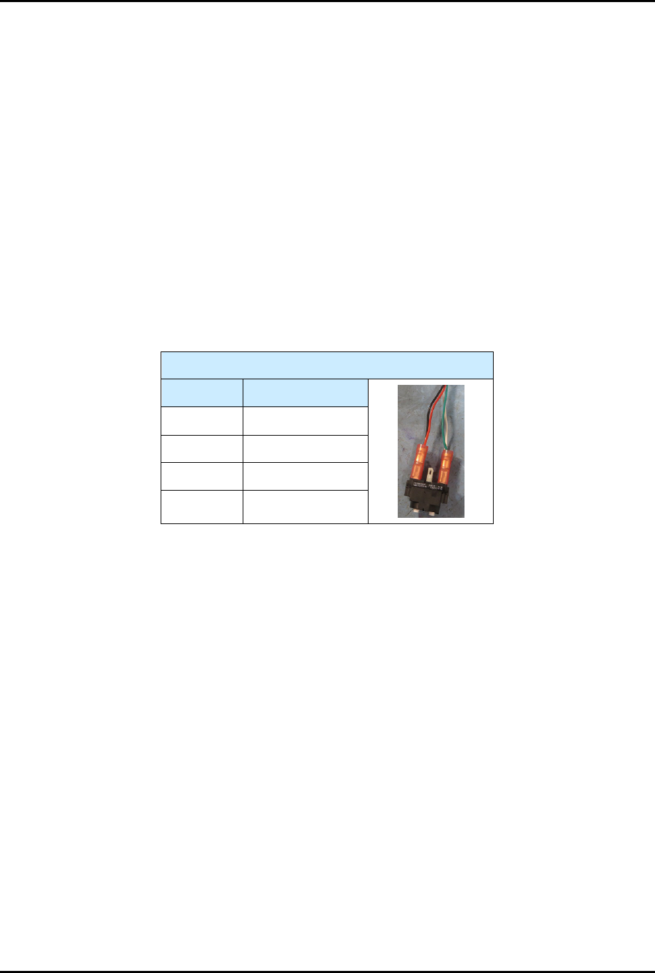
Table 8-3 Power Control Cable Connections (OFF Switch)
OFF Switch
Contact # Color
11 Black
12 Red
21 White
22
Green
S2-9XXX Series Dispensing System IOM Manual Parts Replacement
© 2023 Nordson Corporation 8-33
8.16 Replacing Components Inside the Lower Front Door
Tools and Materials Needed:
• Hex Key Set (Item 59)
WARNING! Ensure the dispensing system has been completely shutdown before attempting to
remove or install any panel, electrical component, or pneumatic component.
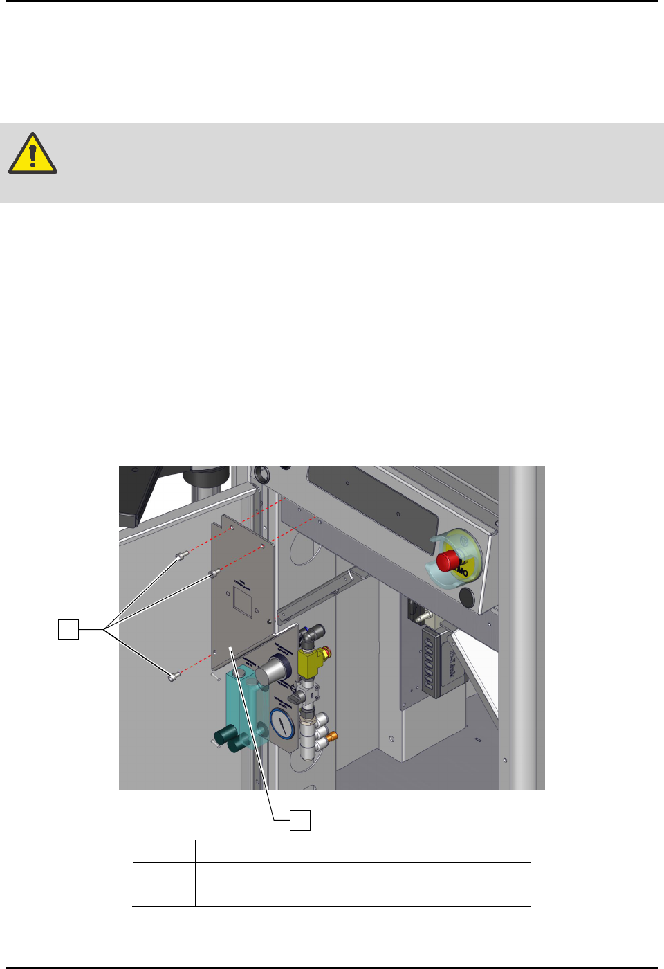
8.16.1 Removing and Installing the Pneumatics Panel
To remove the pneumatics panel (Figure 8-24):
1. Perform a service shutdown, see 2.14 Service Shutdown.
2. Open the lower front door.
3. Rotate the pressure regulator knobs counterclockwise until the pressure gauge registers
zero (0).
4. Remove the three (3) screws and nuts securing the pneumatics panel to the dispensing
system.
5. Remove the pneumatics panel from the dispensing system.
Item
Description
1 Screws
2 Pneumatics Panel
Figure 8-24 Replacing the Pneumatics Panel
2
1
S2-9XXX Series Dispensing System IOM Manual Parts Replacement
8-34 © 2023 Nordson Corporation
To install the pneumatics panel (Figure 8-24):
1. Install the pneumatics panel to the dispensing system with three (3) screws and three (3)
nuts.
2. Rotate the pressure regulator knob counterclockwise until the pressure gauge registers
desired pressure, see 5.10 Adjusting the Air Pressure.
3. Close the lower front door.
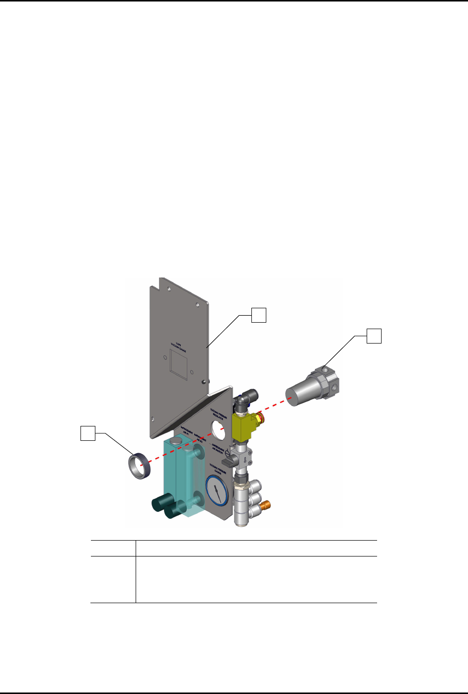
8.16.2 Removing and Installing the Regulator
To remove and install the regulator (Figure 8-25):
1. Remove the pneumatics panel, see 8.14.1 Removing and Installing the Pneumatics Panel.
2. Disconnect the pneumatic connection from the regulator.
Note the connection location.
3. Remove the regulator nut from the front of the pneumatic panel.
4. Remove the regulator from the rear of the pneumatic panel assembly.
Item
Description
1
Regulator Nut
2 Pneumatics Panel
3 FRU, Regulator, E/P, 0-130 psi (Item 49)
Figure 8-25 Replacing the Regulator
3
1
2