3OM-1050-002.pdf - 第151页
*2 [Minimize], [Maximize], [Restore], and [Close] Buttons [Minimize] Button ( ) Minimizing a window hides an edit window . The contents (parameters) of the minimized window are kept un- changed. T o open the hidden windo…
: Close
When pressed, this closes the active file of the component
ID data.
: Save
When pressed, this saves the edited data, replacing the
existing file with the current one.
When a new file is created, it will be saved with a new file
name.
: Save As
When pressed, this saves the edited data with a new name.
: Check
When pressed, this checks if there is any deficiency in the
data of the selected component ID.
: Cascade
When pressed, this overlays the selected windows (com-
ponent ID files) so that you can see each title bar.
: Tile Vertically
When pressed, this re-arranges the selected windows side
by side.
: Tile Horizontally
When pressed, this re-arranges the selected windows up
and down.
01 10-003 3-14 AFO01EDTP
3.1 Toolbar and Icons
*2 [Minimize], [Maximize], [Restore], and [Close] Buttons
[Minimize] Button (
)
Minimizing a window hides an edit window.
The contents (parameters) of the minimized window are kept un-
changed.
To open the hidden window, press the [DATA EDIT] button on the
menu bar and select "CMPNT LBRY" from the menu.
[Maximize] Button (
)
When an edit window is not at its maximum size, this button ap-
pears in the window’s upper-right corner.
When pressed, this enlarges the edit window to its maximum size.
[Restore] Button (
)
When an edit window is already at its maximum size, the [Maxi-
mize] button switches to the [Restore] button, which returns the
window to its previous size.
[Close] Button ( )
When pressed, this closes the active edit window.
*3 Edit Sheet
This sheet enables the operator to edit the parameters of the se-
lected component ID.
01 10-003 3-15
AFO01EDTP
3.1 Toolbar and Icons
3.2 "Shape Data" Tab
3.2.1 "Mold Size" Tab
The corresponding tab sheet appears when "Cylindrical", "Square", "De-
form (Simple)", "IC (Simple)", "IC Complex", "Connector (Simple)", "Con-
nector (Complex)", "Other Leaded (Simple)", or "Other Leaded (Com-
plex)" is selected in the "Component shape" text box.
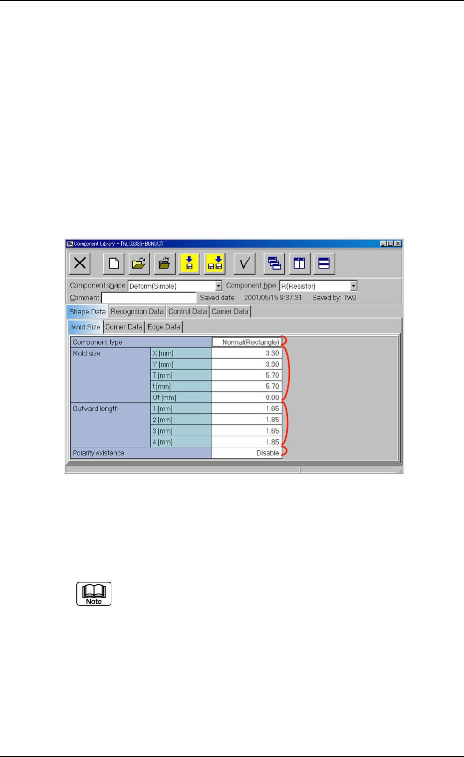
• Sheet Layout
When the "Mold Size" tab is pressed in the "Shape Data" tab sheet,
the following tab sheet appears.
Fig. 3C9 "Shape Data" Tab Sheet ("Deform (Simple)" Selected)
• Sheet Composition
Each parameter is displayed or can be entered.
Refer to "4.1.3 Basic Usage of Text Boxes" for the detailed in-
formation on how to enter each parameter.
(1) Component shape: Cylindrical, Square
*2 Mold size, *4 Polarity existence
01 10-003 3-16
AFO01EDTP
3.2 "Shape Data" Tab
*1
*2
*4
*3