3OM-1050-002.pdf - 第168页
Fig. 3C18 "Control Data" T ab Sheet ("Cylindrical" Selected) *6 Pickup level [mm], *7 Placement level [mm], *8 Pickup pos correction, *9 Auto fdr axis adjustment, *10 Error process, *1 1 Pick-up diffe…
3.4 "Control Data" Tab
The corresponding tab sheet appears when "Cylindrical", "Square", "De-
form (Simple)", "IC (Simple)", "IC (Complex)", "Connector (Simple)",
"Connector (Complex)", "Other Leaded (Simple)", or "Other Leaded
(Complex)" is selected in the "Component shape" text box.
• Sheet Layout
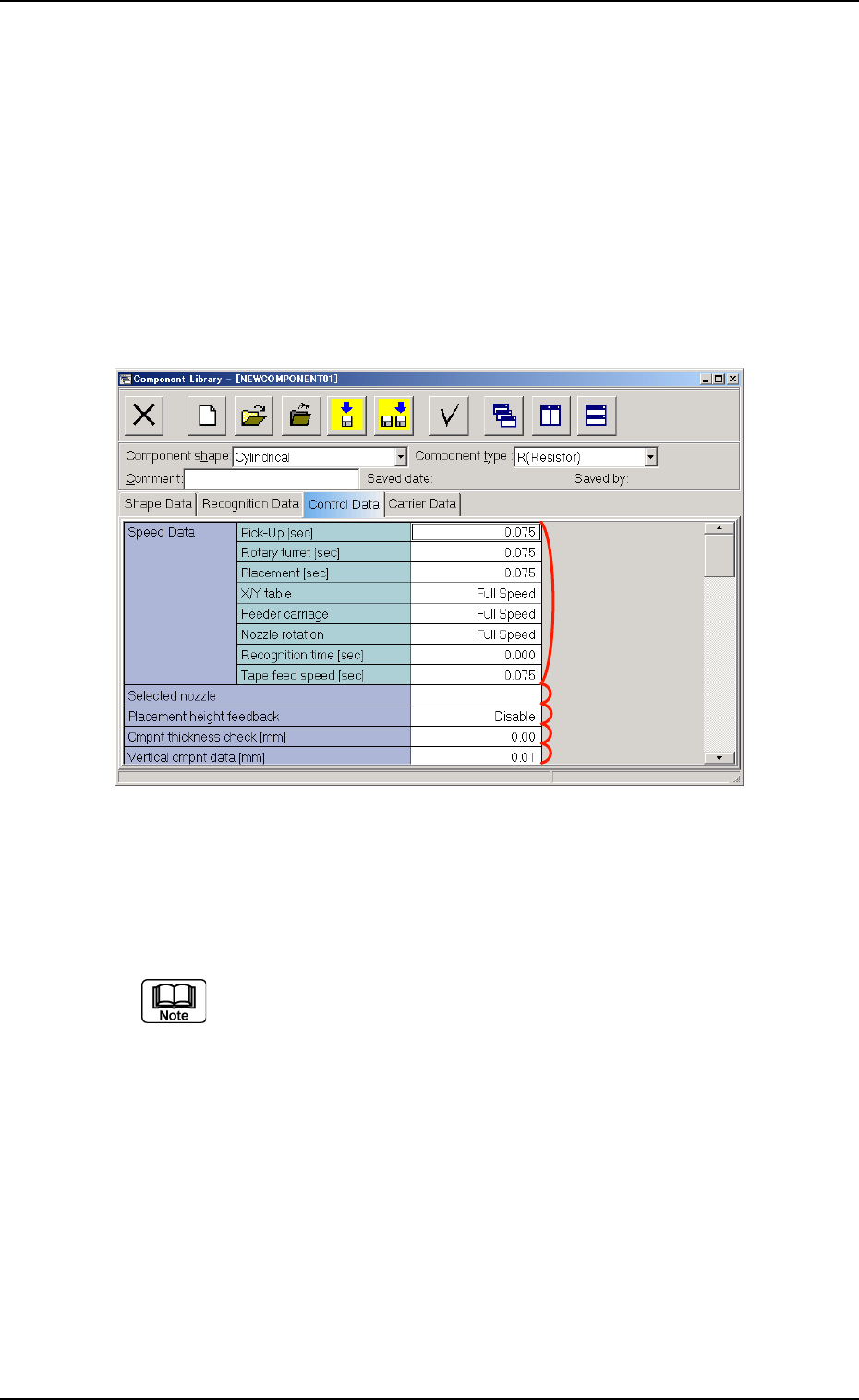
When the "Control Data" tab is pressed, the "Control Data" tab sheet
appears.
Fig. 3C17 "Control Data" Tab Sheet ("Cylindrical" Selected)
• Sheet Composition
Enter a parameter in the text box.
Refer to "4.1.3 Basic Usage of Text Boxes" (Section 2) for the
detailed information on how to enter each parameter.
*1 Speed Data, *2 Selected nozzle,
*3 Placement height feedback, *4 Cmpnt thickness check [mm],
*5 Vertical cmpnt data [mm]
0301-005 3-31
AFO01EDTP
*2
*1
*3
*4
*5
3.4 "Control Data" Tab
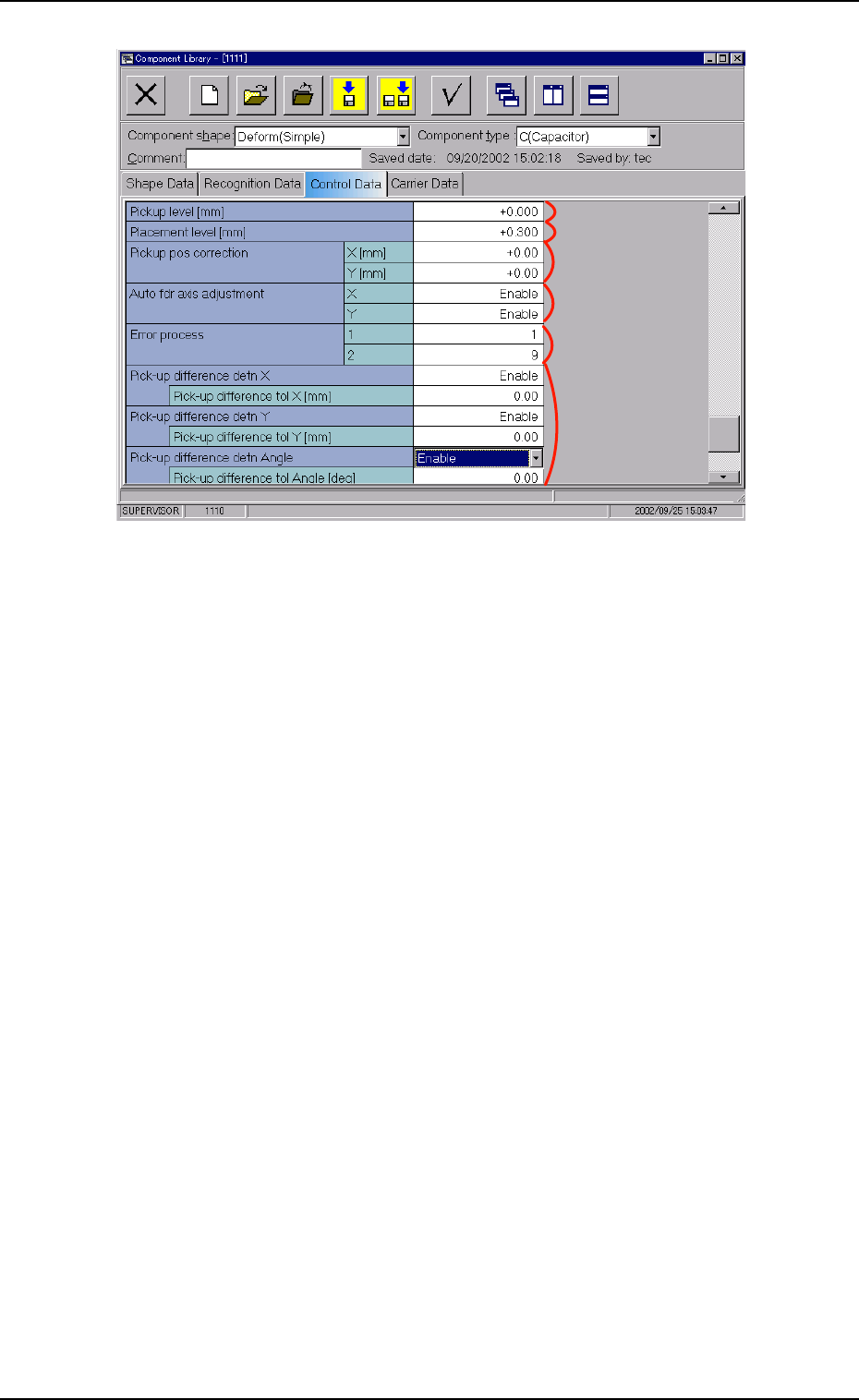
Fig. 3C18 "Control Data" Tab Sheet ("Cylindrical" Selected)
*6 Pickup level [mm], *7 Placement level [mm],
*8 Pickup pos correction, *9 Auto fdr axis adjustment,
*10 Error process, *11 Pick-up difference detn X, Y, Angle
0210-005 3-32
AFO01EDTP
*9
*8
*10
*11
*7
*6
3.4 "Control Data" Tab
3.5 "Carrier Data" Tab
The corresponding tab sheet appears when "Cylindrical", "Square", "De-
form (Simple)", "IC (Simple)", "IC (Complex)", "Connector (Simple)",
"Connector (Complex)", "Other Leaded (Simple)", or "Other Leaded
(Complex)", is selected in the "Component shape" text box.
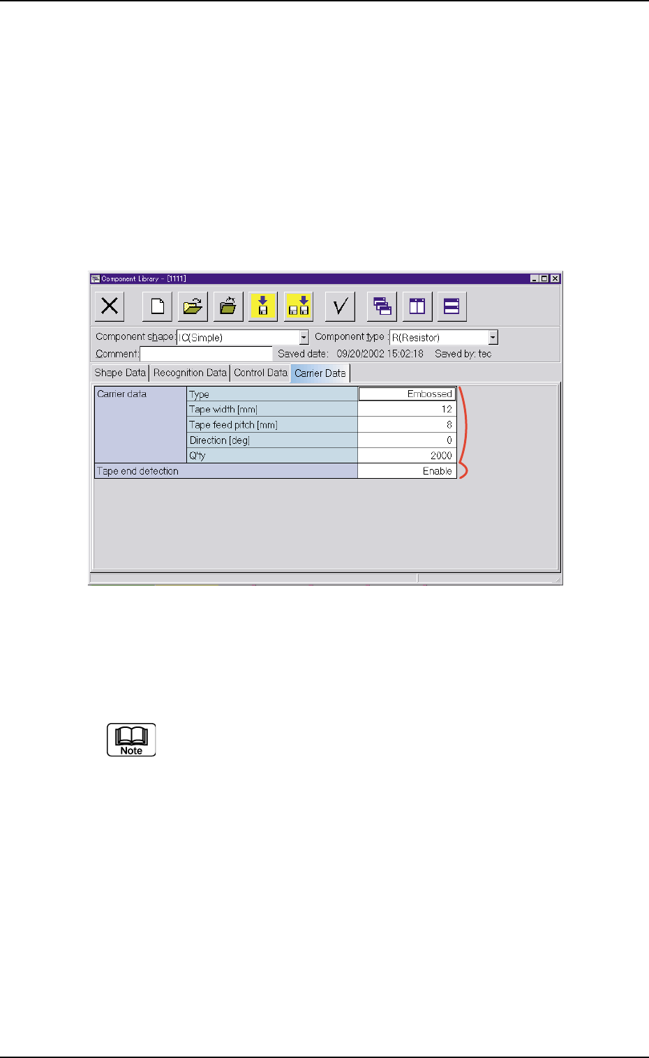
• Sheet Layout
When the "Carrier Data" tab is pressed, the "Carrier Data" tab sheet
appears.
Fig. 3C19 "Carrier Data" Tab Sheet ("Cylindrical" Selected)
• Sheet Composition
Each parameter is displayed or can be entered.
Refer to "4.1.3 Basic Usage of Text Boxes" in "Section 2" for the
detailed information on how to enter parameters.
*1 Carrier Data, *2 Tape end detection
*1
*2
3.5 "Carrier Data" Tab
0210-005 3-33 AFO01EDTP