3OM-1050-002.pdf - 第246页
(1) "Head Origin" T ab • Sheet Layout When the "Head Origin" tab is pressed in the "Head" tab sheet, the fol- lowing tab sheet appears. Fig. 3E18 "Head Origin" T ab Sheet • Sheet C…
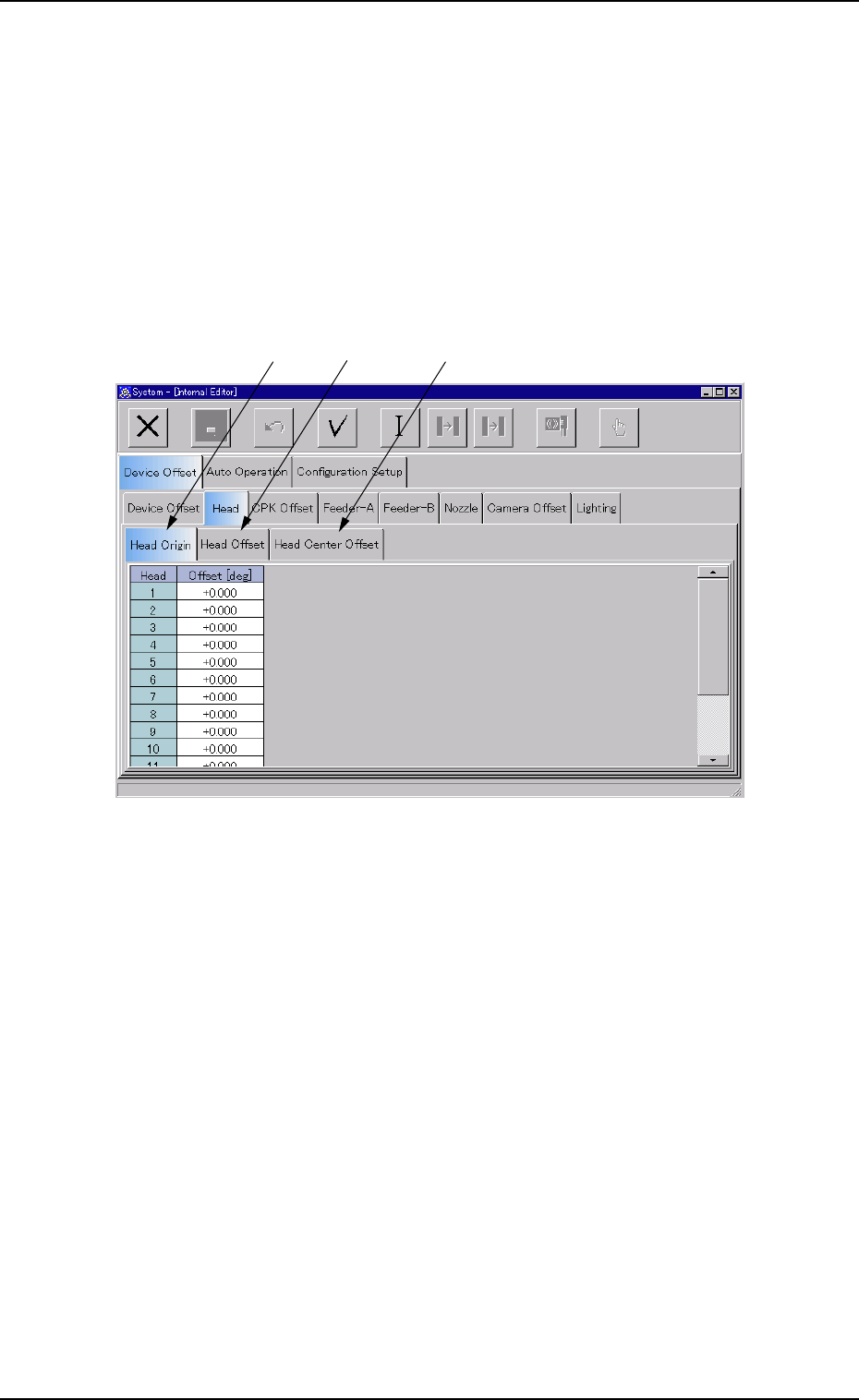
3.2.2 "Head" Tab
The "Head" tab sheet is composed of "Head Origin", "Head Offset", and
"Head Center Offset" tabs.
• Sheet Layout
When the "Head" tab is pressed in the "Device Offset" tab sheet, the
following tab sheet appears.
Fig. 3E17
• Sheet Composition
*1 "Head Origin" Tab
When selected, the "Head Origin" tab sheet appears.
*2 "Head Offset" Tab
When selected, the "Head Offset" tab sheet appears.
*3 "Head Center Offset" Tab
When selected, the "Head Center Offset" tab sheet appears.
0301-004 5-17
AFO01EDTP
*1
*2
*3
3.2 "Device Offset" Tab
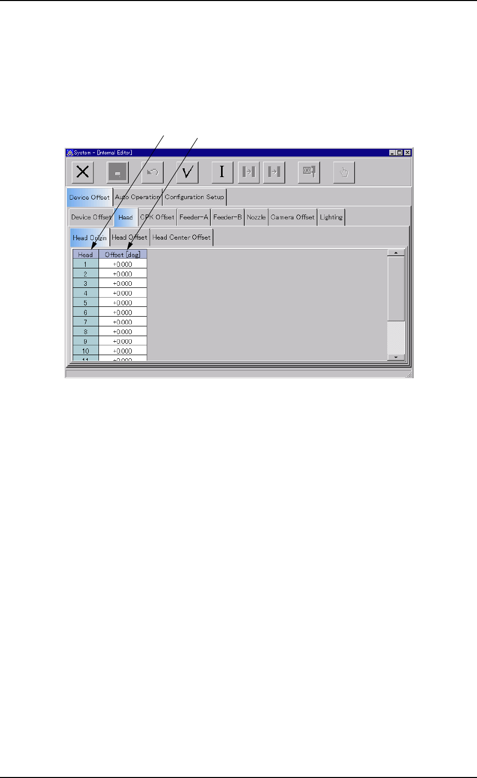
(1) "Head Origin" Tab
• Sheet Layout
When the "Head Origin" tab is pressed in the "Head" tab sheet, the fol-
lowing tab sheet appears.
Fig. 3E18 "Head Origin" Tab Sheet
• Sheet Composition
*1 Head
The head Nos. are displayed.
0301-004 5-18
AFO01EDTP
*1
*2
3.2 "Device Offset" Tab
*2 Offset [
°°
°°
°]
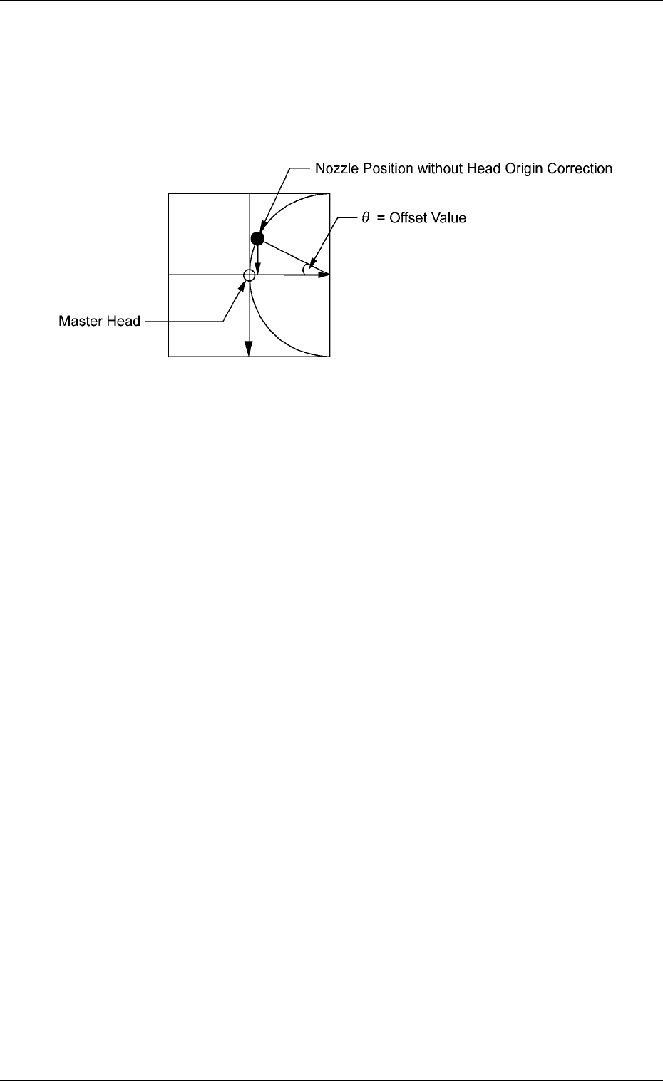
The parameters are used to correct the variations in the origin posi-
tions of the nozzles on each head.
The difference between the master head and the reference value is
automatically calculated through teaching operation.
Fig. 3E19
01 10-003 5-19
AFO01EDTP
3.2 "Device Offset" Tab