3OM-1050-002.pdf - 第41页
(A01_12) Feeder No. offset Set an offset value as an offset of "Fdr No." in the placement feeder location. The placement feeder location data is shifted as much as the speci- fied value and the machine performs…
(A01_10) Feeder standby position
Set a "Fdr No." (feeder slot No.) as a feeder standby position.
000 : This function is disabled.
Entry of "Fdr No." : After a piece of P.C.B. is finished, the feeder
carriage returns to the specified feeder slot
No. (Fdr No. = Pick-Up Position).
Data Input Range
TCM-X100 TCM-X200
101 to 179, 201 to 279, 301 to 379, 401 to 479
TCM-X300
101 to 170, 201 to 270, 301 to 370, 401 to 470
Any feeder slot No. (Fdr No.) which does not exist in the placement feeder
location data cannot be specified.
(A01_11) Alternate mode
Select one of the following options to determine whether or not the
alternate function should be used.
Disable : The alternate function is disabled.
Unit Alternate : The unit alternate function is enabled.
Alternate Pallet : The pallet alternate function is enabled.
The feeder alternate function can be specified in the placement feeder
location data.
0301-005 2-21
AFO01EDTP
2.3 Operation Data
000
Feeder standby position
Fig. 3B26
Alternate mode
Fig. 3B27
Disable
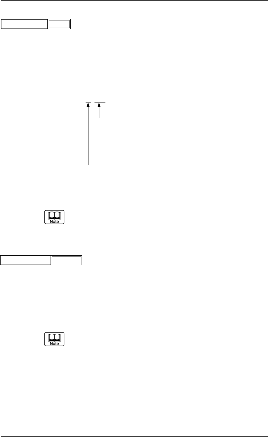
(A01_12) Feeder No. offset
Set an offset value as an offset of "Fdr No." in the placement feeder
location.
The placement feeder location data is shifted as much as the speci-
fied value and the machine performs the pick-up operation.
Data Setting
±{{{
These two digits show the offset in increments of a
feeder location.
Data Input Range
TCM-X100 TCM-X200 : 00 to 79
TCM-X300 : 00 to 70
This digit shows the carriage No. to be shifted.
Data Input Range: 0 to 4
Fig. 3B29
(a) It is recommended that a value with a "+" (plus) sign should be en-
tered.
(b) Set "+000" not to use any offset.
(A01_13) X/Y table accel des
Select one of the following options to determine acceleration of the X/
Y table movement for component placement.
Full Speed 10%Decr 20%Decr 30%Decr
40%Decr 50%Decr 60%Decr 70%Decr
80%Decr 90%Decr
(a) In normal cases, select "Full Speed".
(b) When there are some previously-placed components, the transfer
speed can be decreased in advance to avoid component deviations
that may be caused by the X/Y table movement.
0301-005 2-22
AFO01EDTP
2.3 Operation Data
+000
Feeder No. offset
Fig. 3B28
Full Speed
X/Y table accel des
Fig. 3B30
(A01_14) F1 accel des, F2 accel des, F3 accel des, and F4 accel des
Select one of the following options to determine acceleration of each
feeder carriage movement for component picks.
Full Speed 10%Decr 20%Decr 30%Decr
40%Decr 50%Decr 60%Decr 70%Decr
80%Decr 90%Decr
(A01_15) Recovery regulation
U-N
When placement data is created to cope with the Un-specified multi-
model repetitive pattern function, the recovery regulation must be en-
abled.
Refer to "2.1 Types of P.C.B.’s and Required Data" for de-
tailed information on how to specify "Un".
Disable : The recovery regulation function is disabled.
The normal automatic recovery function is activated.
Enable : The recovery regulation function is enabled.
When the automatic recovery function is activated, a pat-
tern with the smallest "Un" No. is recovered first and the
subsequent patterns are recovered in the ascending or-
der.
As long as all components in the pattern (smaller Un No.)
are not recovered, no components are placed on the sub-
sequent Un No. (Unit).
0210-004 2-23
AFO01EDTP
2.3 Operation Data
F1 accel des
Fig. 3B31
Full Speed
F2 accel des
F3 accel des
F4 accel des
Full Speed
Full Speed
Full Speed
Fig. 3B32
U
-N
Block
Disable
Disable