3OM-1050-002.pdf - 第80页
0210-004 2 - 5 9 AFO01EDTP • Placement Coordinate and Angles (Z=Theta) Fig. 3B1 18 (2) Creation of Operation Data • P .C.B. Data T able 3B18 Placement Coordinate Reference Point X 3 Y 3 X 2 Y 2 X 1 Y 1 Alternate mode Dis…
3. Example of Pattern Program Creation
Described on the following pages are the examples of pattern programs
to be created.
The example of data creation is based on TCM-X200.
As for TCM-X100, the placement coordinate reference is "Rear
Left ".
• Single Pattern
• Single Pattern (P.E.C. Recognition Function Enabled)
• Repetitive Patterns
• Repetitive Patterns (Unit P.C.B. B.B.R. Enabled)
• Repetitive Patterns (Unit P.C.B. B.B.R. Function Enabled)
• Repetitive Patterns (Block Sorting Enabled)
• Repetitive Patterns (Polar Coordinate Conversion Function)
• Multi-Model Repetitive Patterns
3.1 Single Pattern
(1) Information on Pattern Program Creation
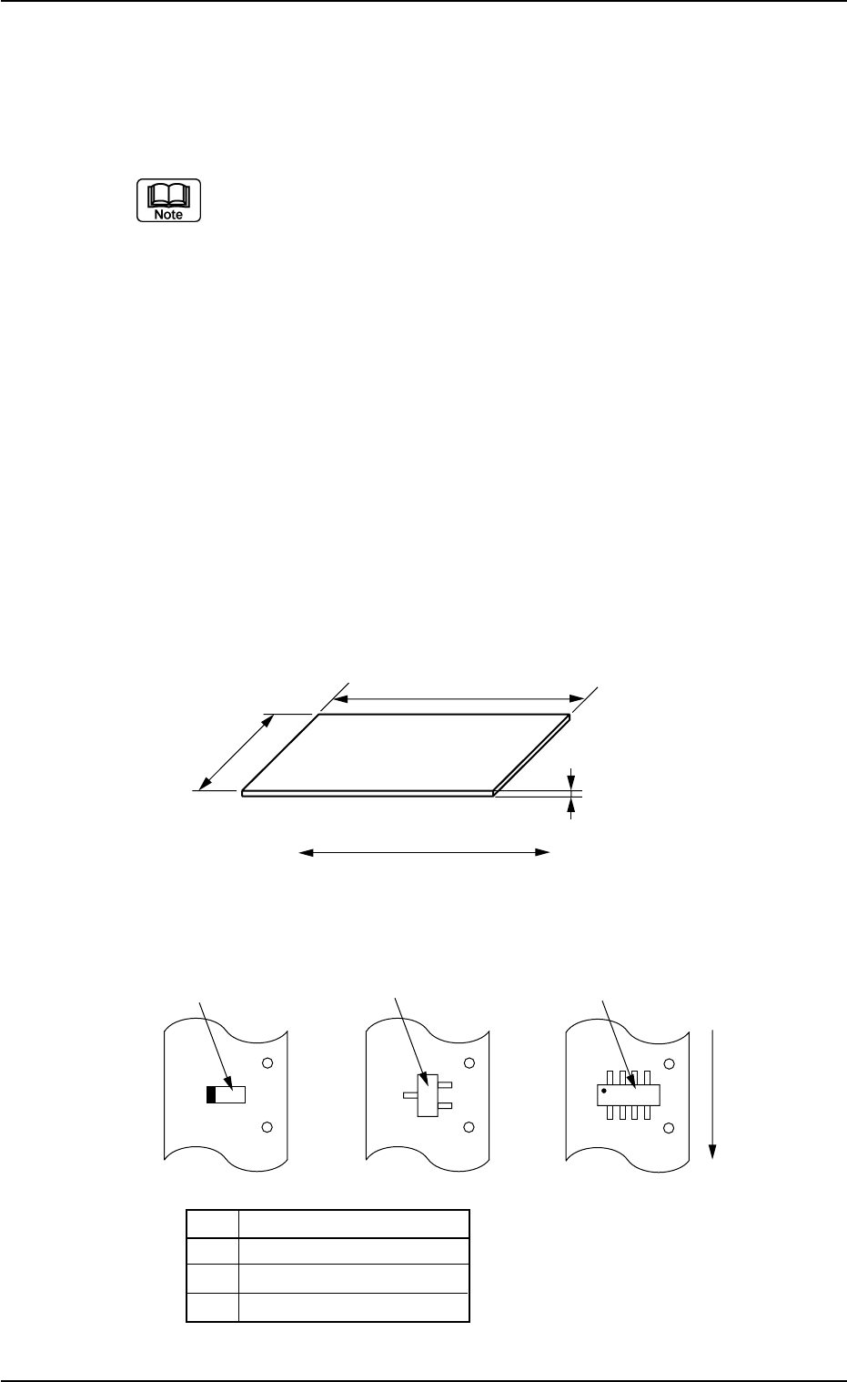
• P.C.B. Size
Fig. 3B116
• Packaged Posture and IDs of Components
No. Component ID
*1 TANA3216B0- - -
*2 TR2012-3B0SANL2
*3 SOP008-B02SAN
Fig. 3B117
0110-003 2-58
AFO01EDTP
3. Example of Pattern Program Creation
250 mm
1.6 mm
P. C. B .
330 mm
P.C.B. Flow Direction
*3
*2
*1
User Direction of
Component Feed
0210-004 2-59 AFO01EDTP
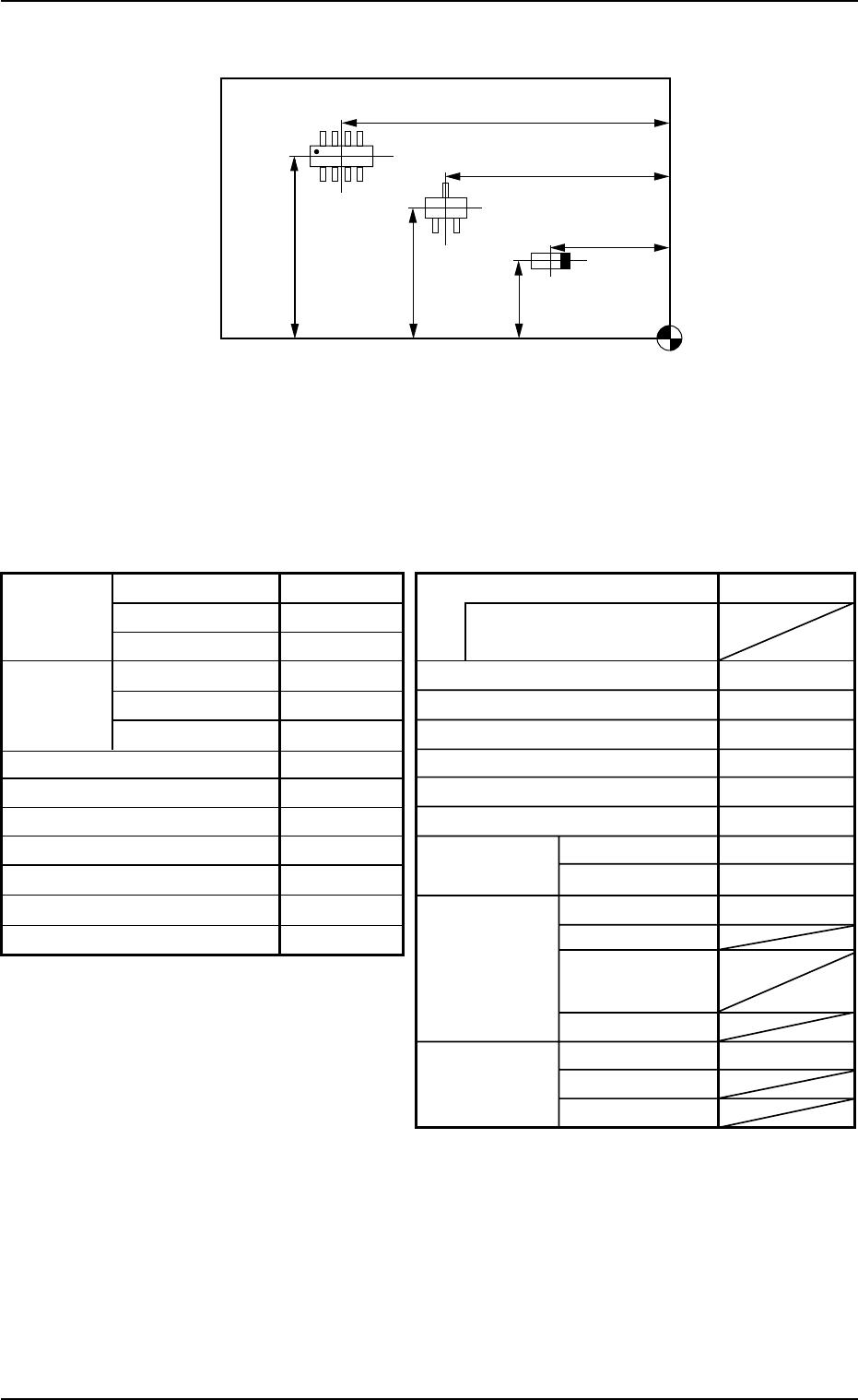
• Placement Coordinate and Angles (Z=Theta)
Fig. 3B118
(2) Creation of Operation Data
• P.C.B. Data
Table 3B18
Placement Coordinate Reference Point
X
3
Y
3
X
2
Y
2
X
1
Y
1
Alternate mode Disable
Alternate carriage data
priority processing
Feeder No. offset +000
X/Y table accel des Full Speed
F1 accel des Full Speed
F2 accel des Full Speed
F3 accel des Full Speed
F4 accel des Full Speed
Recovery U-N Disable
regulation Block Disable
Unit P.C.B. B.B.R.
Mode Disable
Image
Component
prechuck
Sequence
Overall Mode Disable
P.C.B. B.B.R.
X [mm]
Y [mm]
P.C.B. size
P.C.B.
origin offset
X [mm]
Y [mm]
T [mm]
X [mm]
Y [mm]
Z=Theta [deg]
P.C.B. height offset [mm]
P.C.B. Positioning Reference
Pre-Placed component thickness [mm]
Placement mode
P.C.B. transfer speed
Placement data sorting
Feeder standby position
330.000
250.000
1.600
+00.000
+00.000
+0.00
+00.000
Front Right
00.000
Placement
Standard
Standard
000
3.1 Single Pattern
0210-005 2-60 AFO01EDTP
• P.E.C. Recognition Data
Set "Disable" in the "P.E.C. recognition function" text box.
Do not set any parameter in the other text boxes.
• P.E.C. Recognition Mark Data
Do not make this data.
• Setup Data
Create this data when the automatic setup function should be used.
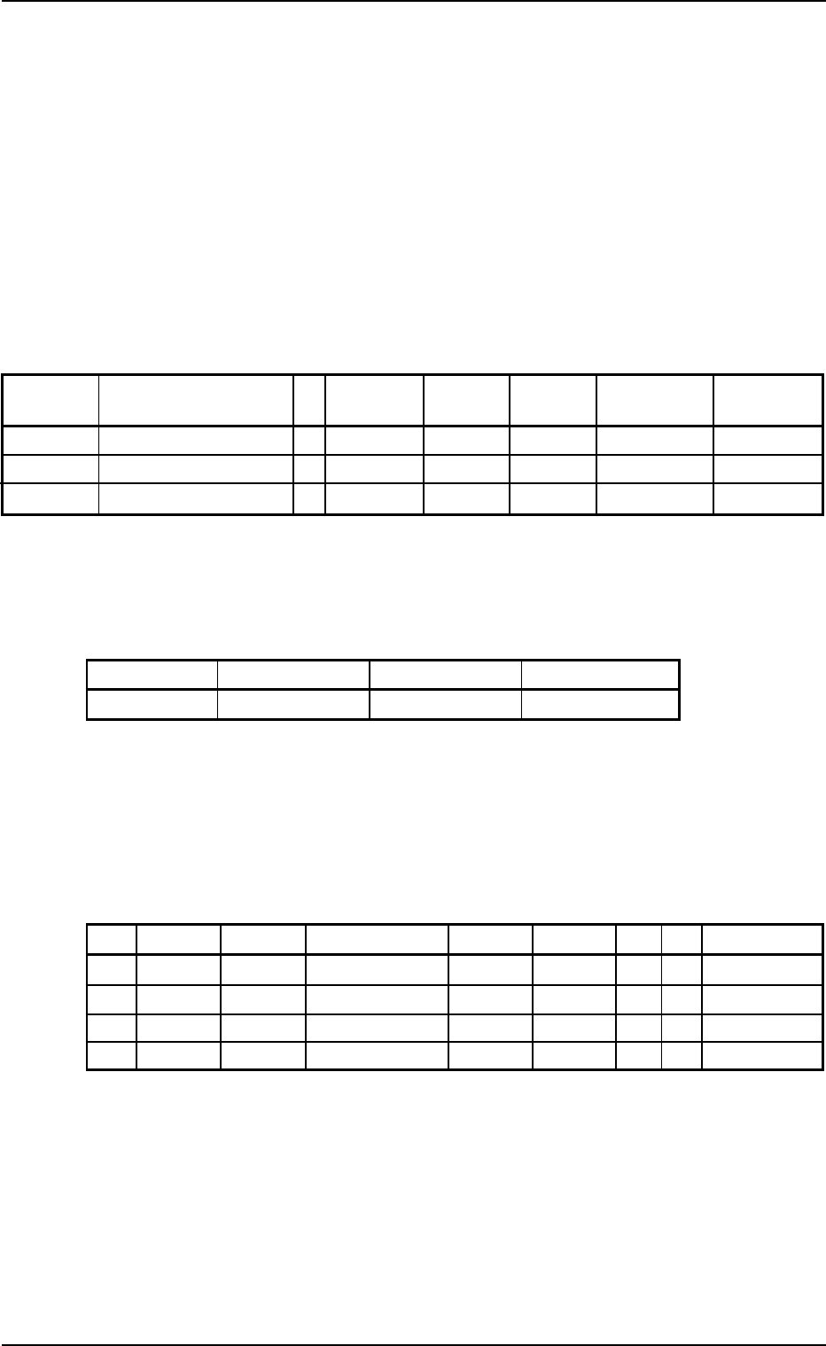
(3) Creation of Placement Feeder Location Data
Table 3B19
Fdr. No. Component ID C Comment Dual Fdr
Feeder Feeder
Fdr. No.
Fixed Alternate
101 TANA3216B0- - - - - Disable Disable 000
103 TR2012-3B0SANL2 - - Disable Disable 000
105 SOP008-B02SAN E - Disable Disable 000
(4) Creation of Placement Data (P-data) U01
• Unit Control
Table 3B20
Unit Control Offset X [mm] Offset Y [mm] Offset Z [deg
]]
]]
]
Placement +000.000 +000.000 +000.00
• Unit P.C.B. B.B.R.
Set "Disable" in this text box.
Do not set any parameter in the other text boxes.
• Placement Data (P-data)
Table 3B21
P-No. X [mm] Y [mm] Z
= =
= =
= theta [deg
]]
]]
] H [mm] Fdr. No. V C Comment
1 X
1
Y
1
+000.00 +0.000 101 00 -
2 X
2
Y
2
+090.00 +0.000 103 00 -
3 X
3
Y
3
+180.00 +0.000 105 00 -
4 +000.000 +000.000 +000.00 +0.000 000 00 E
(5) Creation of Placement Data (O-data) U01
Do not make this data.
3.1 Single Pattern