3OM-1050-002.pdf - 第76页
(C03_03) Z = = = = = theta [deg] Set an angle of each pattern. Keep the angle of the reference pattern as "000°00'". In the figure below , "Pattern 1" is regarded as a reference one. Unit: ° (deg…
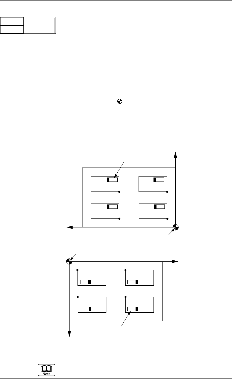
(C03_02) X [mm] and Y [mm]
Set the coordinates of each pattern origin (O
01
through On) based on
the placement coordinate reference point (N
0
).
Unit: mm
A pattern origin refers to the reference coordinates of a repetitive pat-
tern.
The pattern origins (reference coordinates) must be determined, re-
garding the "Z=theta" data as "0°" (described in "(C03_03)" and lo-
cated at corners on the same side as the placement coordinate refer-
ence point (N
0
).
N
0
: The center of
is the placement coordinate reference.
O
01
: Pattern Origin of Pattern 1
O
02
: Pattern Origin of Pattern 2
O
03
: Pattern Origin of Pattern 3
O
04
: Pattern Origin of Pattern 4
Fig. 3B109 Example of Repetitive Patterns
Do not set any coordinates in the last line (last step No.).
Keep them as "000.000".
Placement Coordinate Reference (No)
O
04
Y
X
O
03
O02 O01
Component
Pattern 3Pattern 4
Pattern 2
Pattern 1
Placement Coordinate Reference (No)
O
04
Y
X
O
03
O02
O01
Component
Pattern 3
Pattern 4
Pattern 2
Pattern 1
TCM-X100
TCM-X200 TCM-X300
2.5 Placement Data
0210-004 2-54 AFO01EDTP
Fig. 3B108
X [mm]
Y
[mm]
010.000
010.000
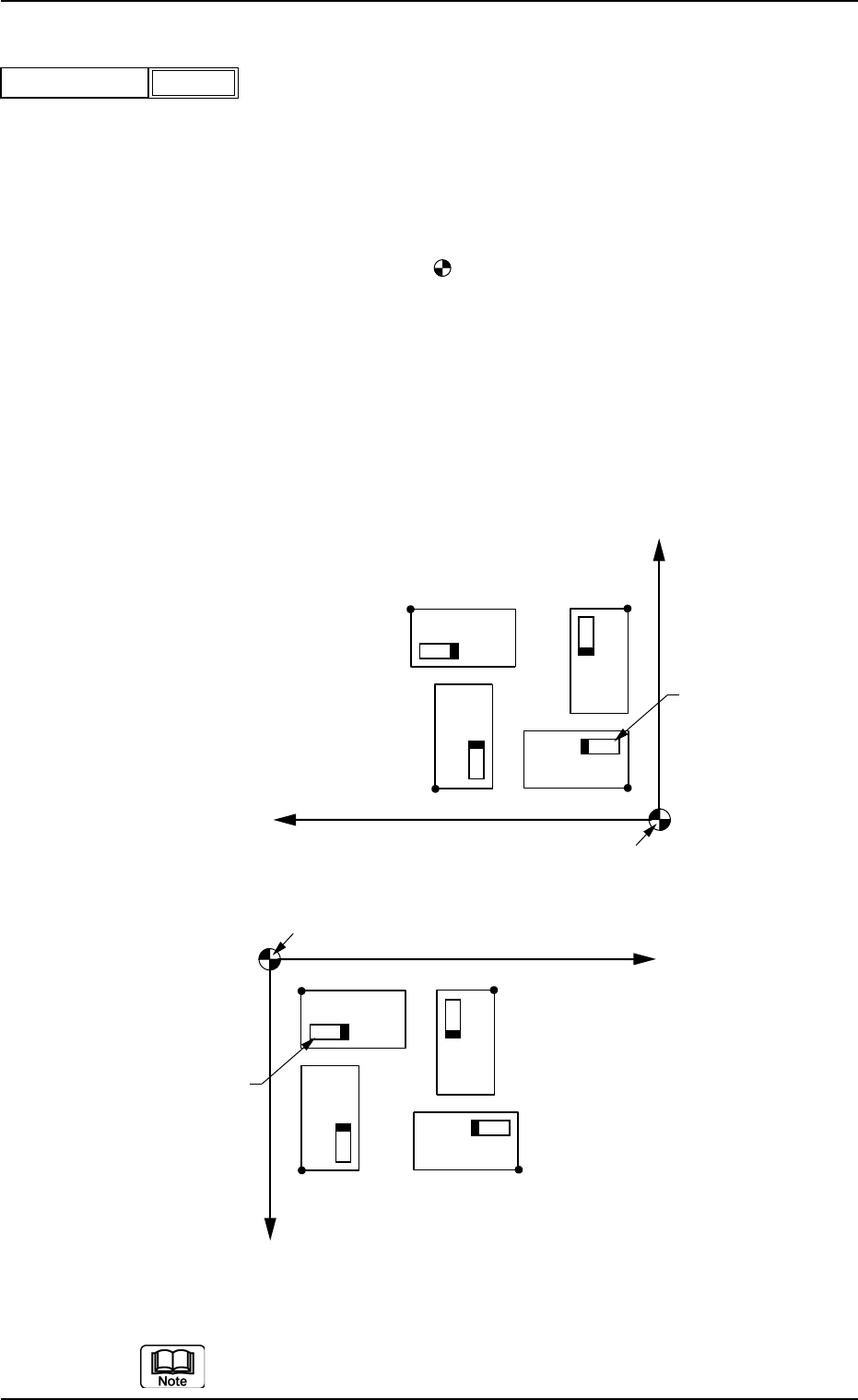
(C03_03) Z
= =
= =
= theta [deg]
Set an angle of each pattern.
Keep the angle of the reference pattern as "000°00'".
In the figure below, "Pattern 1" is regarded as a reference one.
Unit: °(degree)
Data Input Range: ±0°, ±90°, ±180°, or ±270°
N
0
: The center of is the placement coordinate reference.
O
01
: Pattern Origin of Pattern 1
O
02
: Pattern Origin of Pattern 2
O
03
: Pattern Origin of Pattern 3
O
04
: Pattern Origin of Pattern 4
Pattern 1: 0° Pattern 2: 90°
Pattern 3: 180° Pattern 4: 270°
Fig. 3B111 Example of Repetitive Patterns
Do not set any angle in the last line (last step No.).
Keep it as "+000.00".
Placement Coordinate Reference (N0)
X
O01
Component
Pattern 1
Pattern 3
Pattern 2
Pattern 4
O04
O03
O02
Y
Placement Coordinate Reference (N0)
X
O01
Component
Pattern 1
Pattern 3
Pattern 2
Pattern 4
O04
O03
O02
Y
TCM-X100
TCM-X200 TCM-X300
2.5 Placement Data
0301-005 2-55 AFO01EDTP
Fig. 3B110
+000.00
Z = theta [deg]
(C03_04) C
Enter some of the following control commands.
CAUTION
If a control command other than the following ones is
used, the step becomes invalid.
- (hyphen): This command handles the steps as those for compo-
nent placement.
S:This command invalidates the steps specified as those
for component placement.
C:This command invalidates the steps specified as those
for component placement.
Note : As for dispensers, these steps become valid.
D:This command handles the steps as those for compo-
nent placement.
Note : As for dispensers, these steps become invalid.
E:When placement data (O) is not created, this shows
the end of the steps in the placement data (P).
Confirm that "0" (zero) is set in the "X [mm]", "Y [mm]", "Z=theta", "B-X
[mm]", and "B-Y [mm]" and set "E".
(C03_05) Comment
Set a comment for each step No.
Up to 32 characters (alphanumerics and marks) can be used.
The automatic operation is not affected by these comments.
2.5 Placement Data
0207-004 2-56 AFO01EDTP
Fig. 3B112
-
C
-
Comment
Fig. 3B113