3OM-1050-002.pdf - 第93页
3 . 6 Repetitive Patterns (Block Sorting Enabled) Follow the same procedure as described in "3.4 Repetitive Patterns (Unit P .C.B. B.B.R. Enabled)" except for "Placement Data (P-data)". (1) Informatio…
(4) Creation of Placement Data (P-data) U01
• Unit Control
Follow the same procedure as described in "3.1 Single Pattern".
• Unit P.C.B. B.B.R.
Set "Disable" in this text box.
Do not set any parameter in the other text boxes.
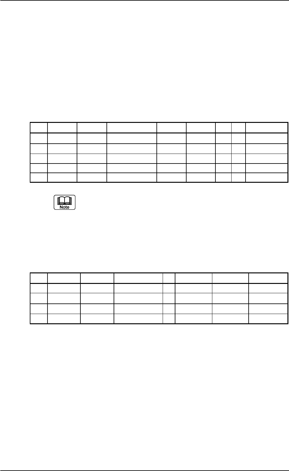
• Placement Data (P-data)
Table 3B32
P-No. X [mm] Y [mm] Z = theta [deg] H [mm] Fdr. No. V C Comment
1 BX
1
BY
1
+000.00 +0.000 000 00 B
2 X
1
Y
1
+000.00 +0.000 101 00 -
3 X
2
Y
2
+090.00 +0.000 103 00 -
4 X
3
Y
3
+180.00 +0.000 105 00 -
5 +000.000 +000.000 +000.00 +0.000 000 00 P
(a) Set the coordinates (BX
1
, BY
1
) of the bad mark in the "X
[mm]" and "Y [mm]" text boxes and "B" (control com-
mand) in the "C" text box of the "P-No. 1" step.
(b) Set "P" or "Q" as a control command in the last line (last
step No.).
(5) Creation of Placement Data (O-data) U01
Table 3B33
O-No. X [mm] Y [mm] Z = theta [deg] C Comment B-X [mm] B-Y [mm]
1 OX
1
OY
1
+000.00 - +000.000 +000.000
2 OX
2
OY
2
+000.00 - +000.000 +000.000
3 OX
3
OY
3
+000.00 - +000.000 +000.000
4 +000.000 +000.000 +000.00 E +000.000 +000.000
0210-005 2-71 AFO01EDTP
3.5 Repetitive Patterns (Unit P.C.B. B.B.R. Function Enabled)

3.6 Repetitive Patterns (Block Sorting Enabled)
Follow the same procedure as described in "3.4 Repetitive Patterns
(Unit P.C.B. B.B.R. Enabled)" except for "Placement Data (P-data)".
(1) Information on Pattern Program Creation
• Example of Patterns
Fig. 3B127 General View
Fig. 3B128 Pattern 1 (Magnified View)
• X/Y Table Speed for Components
(Component Library Data)
C1 and C2: Full Speed
C3 and C4: 20%Decr
C5 and C6: 50%Decr
0110-003 2-72
AFO01EDTP
Placement Coordinate
Reference Point
Pattern 1
Pattern 2
Pattern 3
Placement Coordinate
Reference Point
C6
(X
6
, Y
6
)
(X
4
, Y
4
)
(X
2
, Y
2
)
(X
1
, Y
1
)
(X
3
, Y
3
)
(X
5
, Y
5
)
C4
C2
C3
C1
C5
3.6 Repetitive Patterns (Block Sorting Enabled)
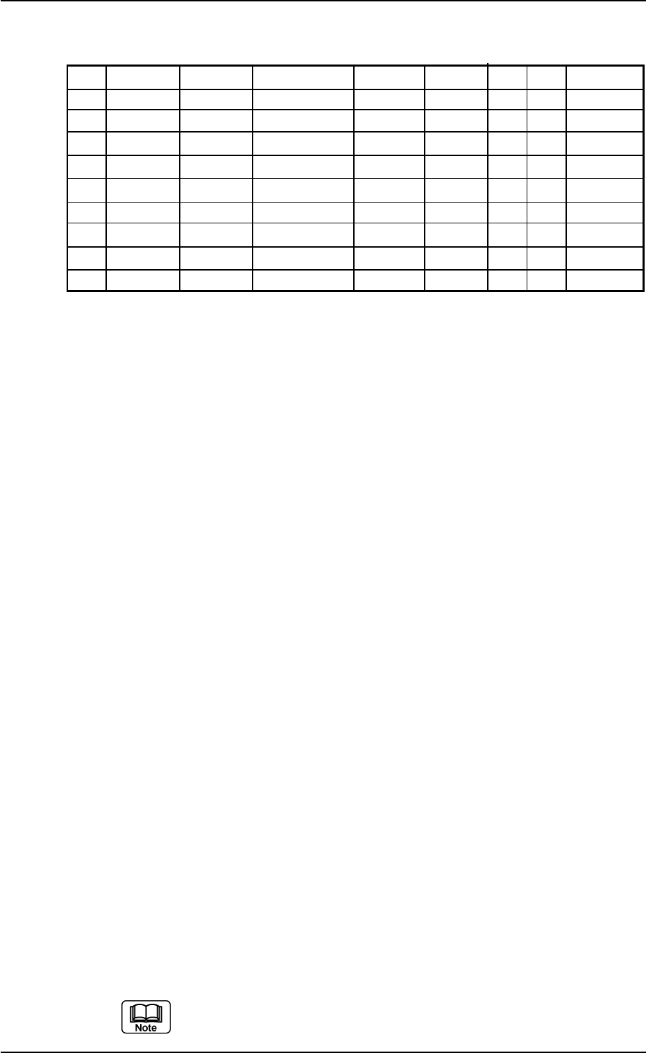
(2) Creation of Placement Data (P-data)
Table 3B34
P-No. X [mm] Y [mm] Z = theta [deg] H [mm] Fdr. No. V C Comment
1 X
1
Y
1
Z
1
+0.000 XXX 00 - C1
2 X
2
Y
2
Z
2
+0.000 XXX 00 - C2
3 +000.000 +000.000 +000.00 +0.000 000 00 2
4 X
3
Y
3
Z
3
+0.000 XXX 00 - C3
5
X
4
Y
4
Z
4
+0.000 XXX 00 - C4
6 +000.000 +000.000 +000.00 +0.000 000 00 5
7
X
5
Y
5
Z
5
+0.000 XXX 00 - C5
8 X
6
Y
6
Z
6
+0.000 XXX 00 - C6
9 +000.000 +000.000 +000.00 +0.000 000 00 P
Procedure
(2-1) Classify the components into some pairs of groups that indi-
vidually require the same speeds of the X/Y table movement.
Allocate a pair groups of components that require the least
deceleration rate to the smallest "P-No." steps.
In this example, the parameters related to C1 and C2 are set
in the "P-No. 1" and "P-No. 2" steps.
(2-2) Set "2" in the "C" text box of the "P-No. 3" step and "0" (zero)
for the other data.
This step is handled as a delimiter of speed groups.
Notes: (a) The machine does not place any components for
the step where a delimiter of speed groups is speci-
fied.
(b) Control Command "2" does not mean that it is used
to control the speed of the X/Y table movement.
Any of the control commands (0 to 9) can be used
as a delimiter.
In this example, "2" is used to indicate that the com-
ponents in the "P-No. 4" step and the subsequent
ones require the 20% deceleration rate.
(2-3) Follow the same procedure to create each step as described
below.
• Set C3 and C4 in the "P-No. 4" and "P-No. 5" steps.
• Set "5" in the "C" text box of the "P-No. 6" step and "0" (zero)
for the other data.
• Set C5 and C6 in the "P-No. 7" and "P-No. 8" steps.
(2-4) Create the last step in the same way as a normal program. Be
sure to set "P" as a control command in the "C" text box.
Note: Actual component placement will be made in almost
the reverse sequence as explained below.
Up to 20 speed groups can be created in one pattern pro-
gram.
0210-005 2-73
AFO01EDTP
3.6 Repetitive Patterns (Block Sorting Enabled)