3OM-1050-002.pdf - 第261页
(3) "Nozzle Position" T ab • Sheet Layout When the "Nozzle Position" tab is pressed in the "Nozzle" tab sheet, the following tab sheet appears. Fig. 3E32 "Nozzle Position" T ab She…

0207-004 5-32 AFO01EDTP
*2 Nozzle #1 X [mm], Nozzle #1 Y [mm], Nozzle #2 X [mm],
Nozzle #2 Y [mm], Nozzle #3 X [mm], Nozzle #3 Y [mm],
Nozzle #4 X [mm], Nozzle #4 Y [mm], Nozzle #5 X [mm],
Nozzle #5 Y [mm]
Each text box shows an offset value of nozzle position based on the
center of the component recognition camera (Camera #2 Low Mag-
nification) at component recognition of each nozzle.
(a) These offset values are automatically calculated through
teaching operation.
(b) All nozzle positions are recognized by Camera #1 (high
magnification) while the teaching operation is imple-
mented.
At this time, nozzle position high magnification offset
values are calculated.
The low magnification offset values (these parameters)
are calculated through conversion using the offset val-
ues between Camera #1 and Camera #2 (low magnifi-
cation).
Nozzles are not recognized directly by the low magnifi-
cation camera.
(c) Signs (+ and -) are defined in the same way as the
nozzle position high magnification offset.
3.2 "Device Offset" Tab
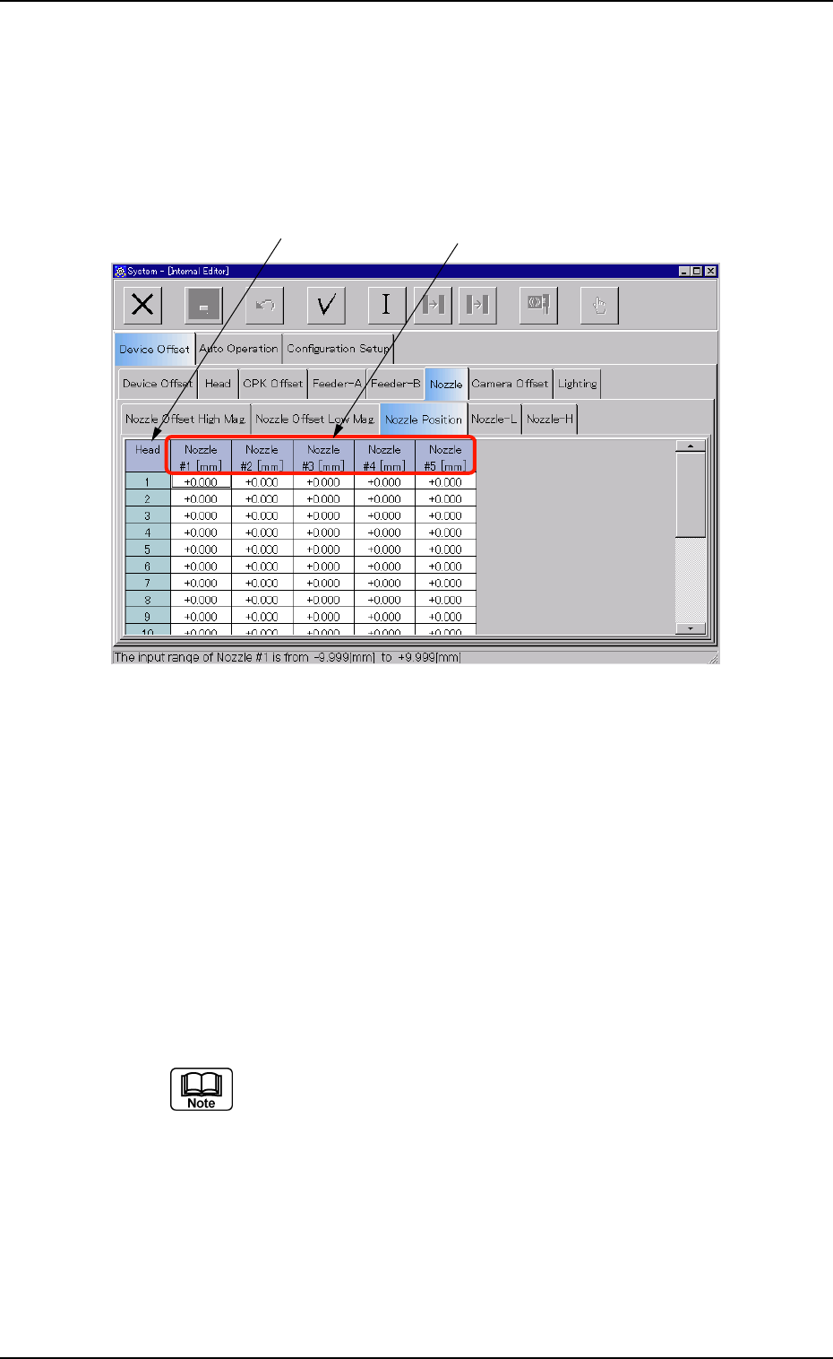
(3) "Nozzle Position" Tab
• Sheet Layout
When the "Nozzle Position" tab is pressed in the "Nozzle" tab sheet, the
following tab sheet appears.
Fig. 3E32 "Nozzle Position" Tab Sheet
• Sheet Composition
*1 Head
The head Nos. are displayed.
*2 Nozzle #1 [mm], Nozzle #2 [mm], Nozzle #3 [mm], Nozzle #4
[mm], Nozzle #5 [mm]
Each text box shows an offset value that is used to manage the
distance (rotation radius) between the head rotational center and
each nozzle.
(a) These parameters are used to calculate the track of
nozzle rotation for pickup position correction.
Plus or minus values are allocated on the basis of the
design value (R = 7.500 mm).
(b) These offset parameters are automatically calculated
through teaching operation.
0301-005 5-33
AFO01EDTP
*1
*2
3.2 "Device Offset" Tab
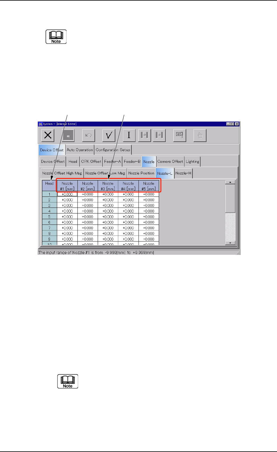
(4) "Nozzle-L" and "Nozzle-H" Tabs
Follow the same procedure for the "Nozzle-H" tab sheet.
• Sheet Layout
When the "Nozzle-L" tab is pressed in the "Nozzle" tab sheet, the fol-
lowing tab sheet appears. When the "Nozzle-H" tab is pressed, almost
the same tab sheet appears.
Fig. 3E33 "Nozzle-L" Tab Sheet
• Sheet Composition
*1 Head
The head Nos. are displayed.
*2 Nozzle #1 [mm], Nozzle #2 [mm], Nozzle #3 [mm], Nozzle #4
[mm], Nozzle #5 [mm]
Each text box shows an offset value that is used to correct varia-
tions in each nozzle height when the nozzle U/D selector (L/H se-
lection) is set to "L" (Low Level) or "H" (High Level).
(a) A plus or minus value is allocated according to the level
variation of each nozzle compared with the origin of the
linear measure detection sensor.
(b) When a nozzle is located above the origin level of the
linear measure detection sensor, a minus (-) value
must be entered as the offset data.
0301-006 5-34
AFO01EDTP
*1 *2
3.2 "Device Offset" Tab