3OM-1050-002.pdf - 第96页
3 . 7 Repetitive Patterns (Polar Coordinate Conversion Function) Follow the same procedure as described in "3.4 Repetitive Patterns (Unit P .C.B. B.B.R. Enabled)" except for "Placement Data (O-data)".…

Order of Component Placement
The machine starts the placement operation with the components
that require less deceleration rate (deceleration of X/Y table move-
ment) as follows.
Pattern 1 (C1 Æ C2) Æ Pattern 2 (C1 Æ C2) Æ Pattern 3 (C1 Æ C2) Æ
Pattern 3 (C3 Æ C4) Æ Pattern 2 (C3 Æ C4) Æ Pattern 1 (C3 Æ C4) Æ
Pattern 1 (C5 Æ C6) Æ Pattern 2 (C5 Æ C6) Æ Pattern 3 (C5 Æ C6) Æ
Placement Data (O-data)
Follow the normal procedure to create this data.
Placement-Speed-Related Component Library Data
The following component library data also gives some effect to the
placement speed. (For your reference)
Speed Data: Pick-Up [sec], Rotary turret [sec], Placement [sec]
Feeder carriage, Recognition time [sec]
Refer to "COMPONENT LIBRARY (TCM-X Series)" for de-
tails of each speed data. (Another Instruction Manual)
0110-003 2-74
AFO01EDTP
3.6 Repetitive Patterns (Block Sorting Enabled)
3.7 Repetitive Patterns (Polar Coordinate
Conversion Function)
Follow the same procedure as described in "3.4 Repetitive Patterns
(Unit P.C.B. B.B.R. Enabled)" except for "Placement Data (O-data)".
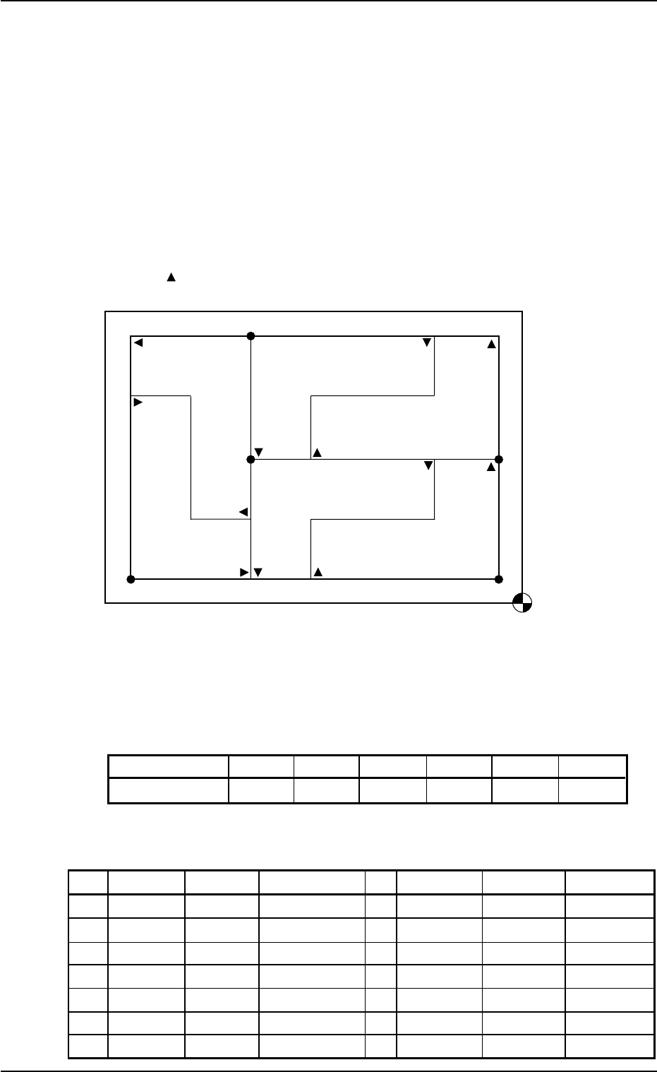
(1) Information on Pattern Program Creation
• Example of Patterns
Fig. 3B129
• Coordinates of Each Pattern Origin
Table 3B35
Pattern Origins O
1
O
2
O
3
O
4
O
5
O
6
Coordinates (X
1
,Y
1
)(X
2
,Y
2
)(X
1
,Y
2
)(X
2
,Y
3
)(X
2
,Y
3
)(X
3
,Y
1
)
(2) Creation of Placement Data (O-data)
Table 3B36
O-No. X [mm] Y [mm] Z = theta [deg] C Comment B-X [mm] B-Y [mm]
1 X
1
Y
1
+000.00 - +000.000 +000.000
2 X
2
Y
2
+180.00 - +000.000 +000.000
3 X
1
Y
2
+000.00 - +000.000 +000.000
4 X
2
Y
3
+180.00 - +000.000 +000.000
5 X
2
Y
3
+090.00 - +000.000 +000.000
6 X
3
Y
1
+270.00 - +000.000 +000.000
7 +000.000 +000.000 +000.00 E +000.000 +000.000
0210-004 2-75 AFO01EDTP
Placement Coordinate
Reference Point
O
4
O
1
O
3
O
2
O
6
Pattern 4 (180°)
Pattern 2 (180°)
Pattern 6
(270°)
Pattern 5
(90°)
Pattern 3 (0°)
Pattern 1 (0°)
O
5
is a fiducial mark.
Assume that Pattern 1 is "0°".
3.7 Repetitive Patterns (Polar Coordinate Conversion Function)
3.8 Multi-Model Repetitive Patterns
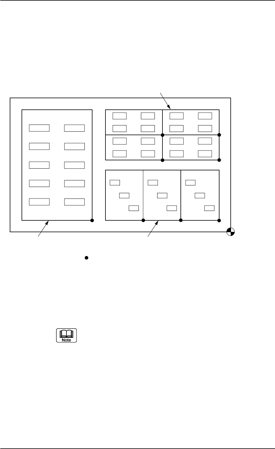
(1) Information on Pattern Program Creation
• Example of Patterns
The following multi-unit P.C.B. consists of three unit P.C.B.’s for Mod-
els A, B, and C.
Fig. 3B130
(2) Creation of Operation Data
Follow the same procedure as described in "3.1 Single Pattern".
The created data is commonly used for Models A, B, and C.
When the unit P.C.B. B.B.R. function or the P.E.C. recog-
nition function is used, be sure to set correct parameters
for the function.
(3) Creation of Placement Feeder Location Data
Follow the same procedure as described in "3.1 Single Pattern".
Note: The created data is commonly used for Models A, B, and C.
0307-004 2-76
AFO01EDTP
Placement Coordinate
Reference Point
Model C Model A
Model B
(OX1,OY1)
( signs are pattern origins.)
3.8 Multi-Model Repetitive Patterns