3OM-1050-002.pdf - 第217页
*2 Recording Date & Time Displayed are the recording date & time and the machine name related to the bypass & rate data. *3 T abs and T ab Sheets The "Bypass & Rate Data" window is provided with…
5. "Bypass & Rate Data" Window
This window enables the operator to check the pick-up rate and nozzle
bypass condition (managed for each individual feeders or nozzles) based
on each pick-up rate and nozzle bypassing specified in the auto opera-
tion setup.
Refer to "3.3.1 "Auto Operation Setup" Tab" in "Section 5" for
the parameter settings of "Auto Operation".
• Window Layout
When the [Comp. Handling Err. Rate Dt.] button in the "Comp. Han-
dling Err. Rate Dt." tab sheet ("Management Data" window) is pressed,
the "Bypass & Rate Data" window opens.
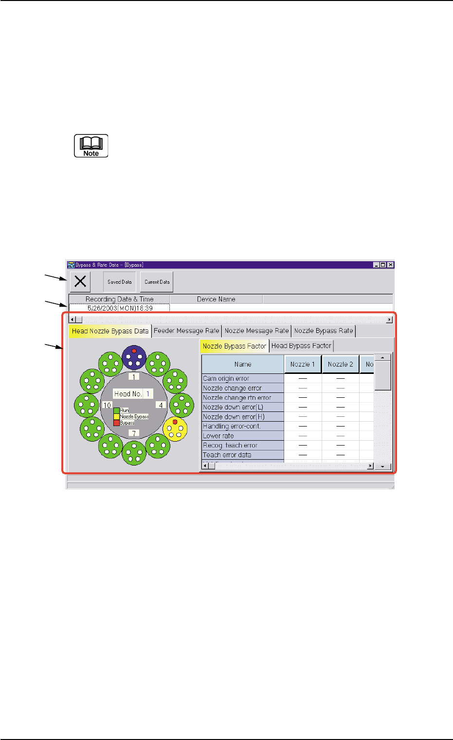
Fig. 3D19 "Bypass & Rate Data" Window
• Window Composition
*1 Toolbar
The following buttons are provided on this bar.
[Close] Button
When this button is pressed, the "Bypass & Rate Data" window
closes.
[Saved Data] Button
When pressed, this button displays the data saved as bypass &
rate data.
[Current Data] Button
When pressed, this button displays the current bypass & rate data.
*1
*2
*3
0307-006 4-40 AFO01EDTP
5. "Bypass & Rate Data" Window

*2 Recording Date & Time
Displayed are the recording date & time and the machine name
related to the bypass & rate data.
*3 Tabs and Tab Sheets
The "Bypass & Rate Data" window is provided with the following
four tab sheets. When a tab is pressed, the corresponding tab sheet
appears inside the window.
Table 3D7
Tabs Description
Head Nozzle Bypass The rotary turret (heads and nozzles) is displayed graphically on the
Data left side of the tab sheet.
When a head (nozzles) is selected on the graphical rotary turret, the
bypass factors are displayed on the right side of the tab sheet.
Feeder Message Rate This tab sheet is provided with four tab sheets - "Feeder Carriage
#1", "Feeder Carriage #2", "Feeder Carriage #3", and "Feeder Car-
riage #4" tab sheets. Each tab sheet displays the pick-up rate, the
feeder message rate, and the component ID that are classified by
each warning factor on individual feeders (actual feeders).
Nozzle Message Rate The corresponding tab sheet displays the pick-up rate and the nozzle
message rate classified by each warning factor on the individual heads
and nozzles.
Nozzle Bypass Rate The corresponding tab sheet displays the pick-up rate and the nozzle
bypass rate classified by each nozzle bypass rate on the individual
heads and nozzles.
0207-004 4-41
AFO01EDTP
5. "Bypass & Rate Data" Window
5.1 "Head Nozzle Bypass Data" Tab
The corresponding tab sheet displays the bypass factors of the heads
or the nozzles.
• Sheet Layout
When the "Head Nozzle Bypass Data" tab is pressed in the "Bypass
& Rate Data" window, the following tab sheet appears inside the win-
dow.
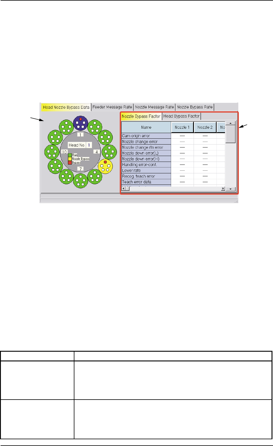
Fig. 3D20 "Head Nozzle Bypass Data" Tab Sheet
("Nozzle Bypass Factor" Tab Sheet)
• Sheet Composition
*1 Graphical Expression of Heads and Nozzles
When a head (nozzles) is selected on the graphical rotary turret,
the nozzle or the head bypass factors are displayed on the right tab
sheets.
*2 Tabs and Tab Sheets
The right side of the "Head Nozzle Bypass Data" tab sheet is occu-
pied by the following two tab sheets.
Table 3D8
Tabs Description
Nozzle Bypass Factor When this tab is selected, the nozzles are expressed graphically on
the left side and the nozzle bypass factors are indicated on the right
tab sheet.
(See Fig. 3D20.)
Head Bypass Factor When this tab is selected, the heads are expressed graphically on
the left side and the head bypass factors are indicated on the right
tab sheet.
(See Fig. 3D21.)
*1
*2
0307-006 4-42 AFO01EDTP
5.1 "Head Nozzle Bypass Data" Tab