3OM-1050-002.pdf - 第81页
0210-005 2 - 6 0 AFO01EDTP • P .E.C. Recognition Data Set "Disable" in the "P .E.C. recognition function" text box. Do not set any parameter in the other text boxes. • P .E.C. Recognition Mark Data Do…
0210-004 2-59 AFO01EDTP
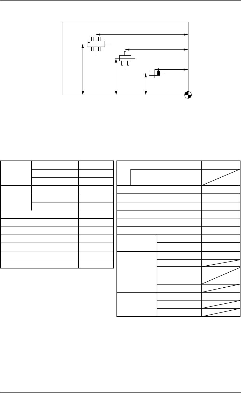
• Placement Coordinate and Angles (Z=Theta)
Fig. 3B118
(2) Creation of Operation Data
• P.C.B. Data
Table 3B18
Placement Coordinate Reference Point
X
3
Y
3
X
2
Y
2
X
1
Y
1
Alternate mode Disable
Alternate carriage data
priority processing
Feeder No. offset +000
X/Y table accel des Full Speed
F1 accel des Full Speed
F2 accel des Full Speed
F3 accel des Full Speed
F4 accel des Full Speed
Recovery U-N Disable
regulation Block Disable
Unit P.C.B. B.B.R.
Mode Disable
Image
Component
prechuck
Sequence
Overall Mode Disable
P.C.B. B.B.R.
X [mm]
Y [mm]
P.C.B. size
P.C.B.
origin offset
X [mm]
Y [mm]
T [mm]
X [mm]
Y [mm]
Z=Theta [deg]
P.C.B. height offset [mm]
P.C.B. Positioning Reference
Pre-Placed component thickness [mm]
Placement mode
P.C.B. transfer speed
Placement data sorting
Feeder standby position
330.000
250.000
1.600
+00.000
+00.000
+0.00
+00.000
Front Right
00.000
Placement
Standard
Standard
000
3.1 Single Pattern
0210-005 2-60 AFO01EDTP
• P.E.C. Recognition Data
Set "Disable" in the "P.E.C. recognition function" text box.
Do not set any parameter in the other text boxes.
• P.E.C. Recognition Mark Data
Do not make this data.
• Setup Data
Create this data when the automatic setup function should be used.
(3) Creation of Placement Feeder Location Data
Table 3B19
Fdr. No. Component ID C Comment Dual Fdr
Feeder Feeder
Fdr. No.
Fixed Alternate
101 TANA3216B0- - - - - Disable Disable 000
103 TR2012-3B0SANL2 - - Disable Disable 000
105 SOP008-B02SAN E - Disable Disable 000
(4) Creation of Placement Data (P-data) U01
• Unit Control
Table 3B20
Unit Control Offset X [mm] Offset Y [mm] Offset Z [deg
]]
]]
]
Placement +000.000 +000.000 +000.00
• Unit P.C.B. B.B.R.
Set "Disable" in this text box.
Do not set any parameter in the other text boxes.
• Placement Data (P-data)
Table 3B21
P-No. X [mm] Y [mm] Z
= =
= =
= theta [deg
]]
]]
] H [mm] Fdr. No. V C Comment
1 X
1
Y
1
+000.00 +0.000 101 00 -
2 X
2
Y
2
+090.00 +0.000 103 00 -
3 X
3
Y
3
+180.00 +0.000 105 00 -
4 +000.000 +000.000 +000.00 +0.000 000 00 E
(5) Creation of Placement Data (O-data) U01
Do not make this data.
3.1 Single Pattern
0301-004 2-61 AFO01EDTP
3.2 Single Pattern (P.E.C. Recognition Function
Enabled)
(1) Information on Pattern Program Creation
• P.C.B. size
Follow the same procedure as described in "3.1 Single Pattern".
• Packaged Posture and IDs of Components
Follow the same procedure as described in "3.1 Single Pattern".
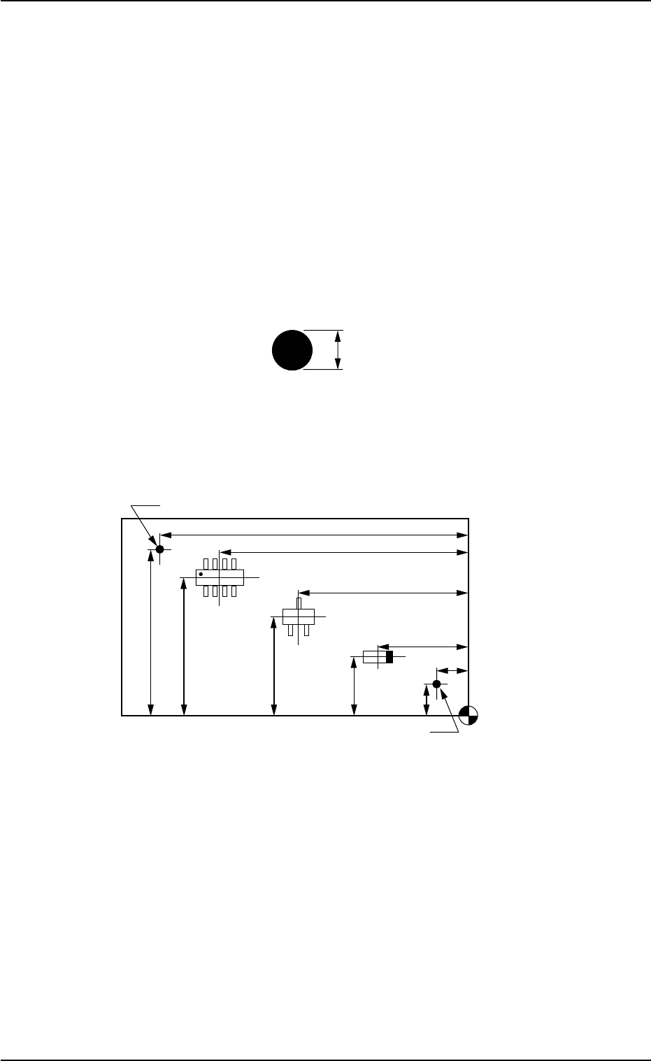
• P.E.C. Recognition Mark Data
Fig. 3B119
• Placement Coordinates & Angles and Coordinates of Fiducial
Marks
Fig. 3B120
1.0 mm
Placement Coordinate
Reference Point
X
3
Y
3
X
2
Y
2
X
1
FX
1
Y
1
FY
1
FY
2
FX
2
Fiducial Mark
Fiducial Mark
3.2 Single Pattern (P.E.C. Recognition Function Enabled)