3OM-1050-002.pdf - 第154页
3.2.2 "Corner Data" T ab The corresponding tab sheet appears when "Cylindrical", "Square", or "Deform (Simple)" is selected in the "Component shape" text box. • Sheet Lay…

01 10-003 3-17 AFO01EDTP
(2) Component shape: Deform (Simple)
*1 Component type, *2 Mold size, *3 Outward length,
*4 Polarity existence
(3) Component Shape: IC (Simple), IC (Complex),
Connector (Simple),
Connector (Complex),
Other Leaded (Simple),
Other Leaded (Complex)
*2 Mold size, *3 Outward length, *4 Polarity existence
3.2 "Shape Data" Tab
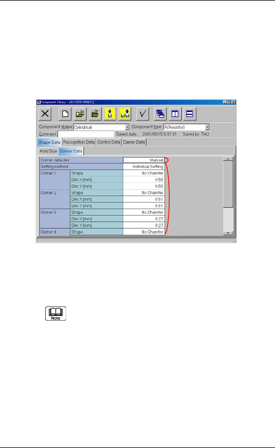
3.2.2 "Corner Data" Tab
The corresponding tab sheet appears when "Cylindrical", "Square", or
"Deform (Simple)" is selected in the "Component shape" text box.
• Sheet Layout
When the "Corner Data" tab is pressed in the "Shape Data" tab sheet,
the following tab sheet appears.
Fig. 3C10 "Corner Data" Tab Sheet ("Cylindrical" Selected)
• Sheet Composition
Each parameter is displayed or can be entered.
Refer to "4.1.3 Basic Usage of Text Boxes" for the detailed in-
formation on how to enter each parameter.
*1 Corner data des
*2 Setting method
Corner 1, Corner 2, Corner 3, Corner 4
Enter a parameter in each text box according to the parameter
(setting condition) selected for "Setting method".
01 10-003 3-18
AFO01EDTP
*1
*2
3.2 "Shape Data" Tab
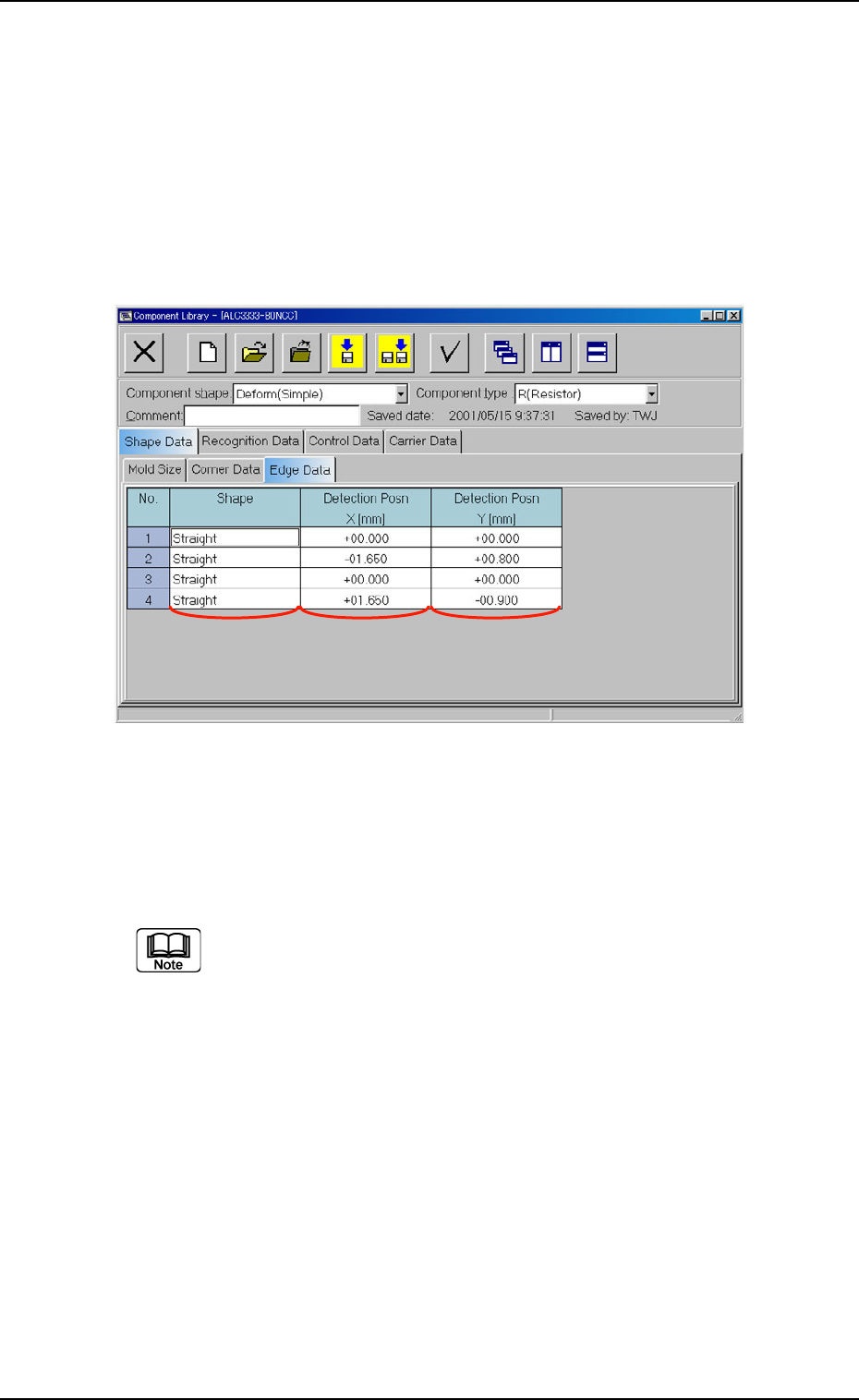
3.2.3 "Edge Data" Tab
The corresponding tab sheet appears when "Deform (Simple)" is se-
lected in the "Component shape" text box.
• Sheet Layout
When the "Edge Data" tab is pressed in the "Shape Data" tab sheet,
the following tab sheet appears.
Fig. 3C11 "Edge Data" Tab Sheet ("Deform (Simple)" Selected)
• Sheet Composition
Each parameter is displayed or can be entered.
Refer to "4.1.3 Basic Usage of Text Boxes" for the detailed infor-
mation on how to enter each parameter.
*1 Shape, *2 Detection Posn X [mm], *3 Detection Posn Y [mm]
01 10-003 3-19
AFO01EDTP
*1
*2 *3
3.2 "Shape Data" Tab