3OM-1050-002.pdf - 第70页
(C02_05) Z = = = = = theta [deg] Set angles for component placement. Unit: ° (degree) The placement angles must be determined according to the pack- aged posture of components on the tape or the bulk feeder . Example : F…
(C02_03) P-No.
Shown are the step Nos. of the placement data (P).
Set coordinates and angles for component placement in the lines of
the step Nos. (P-Nos.).
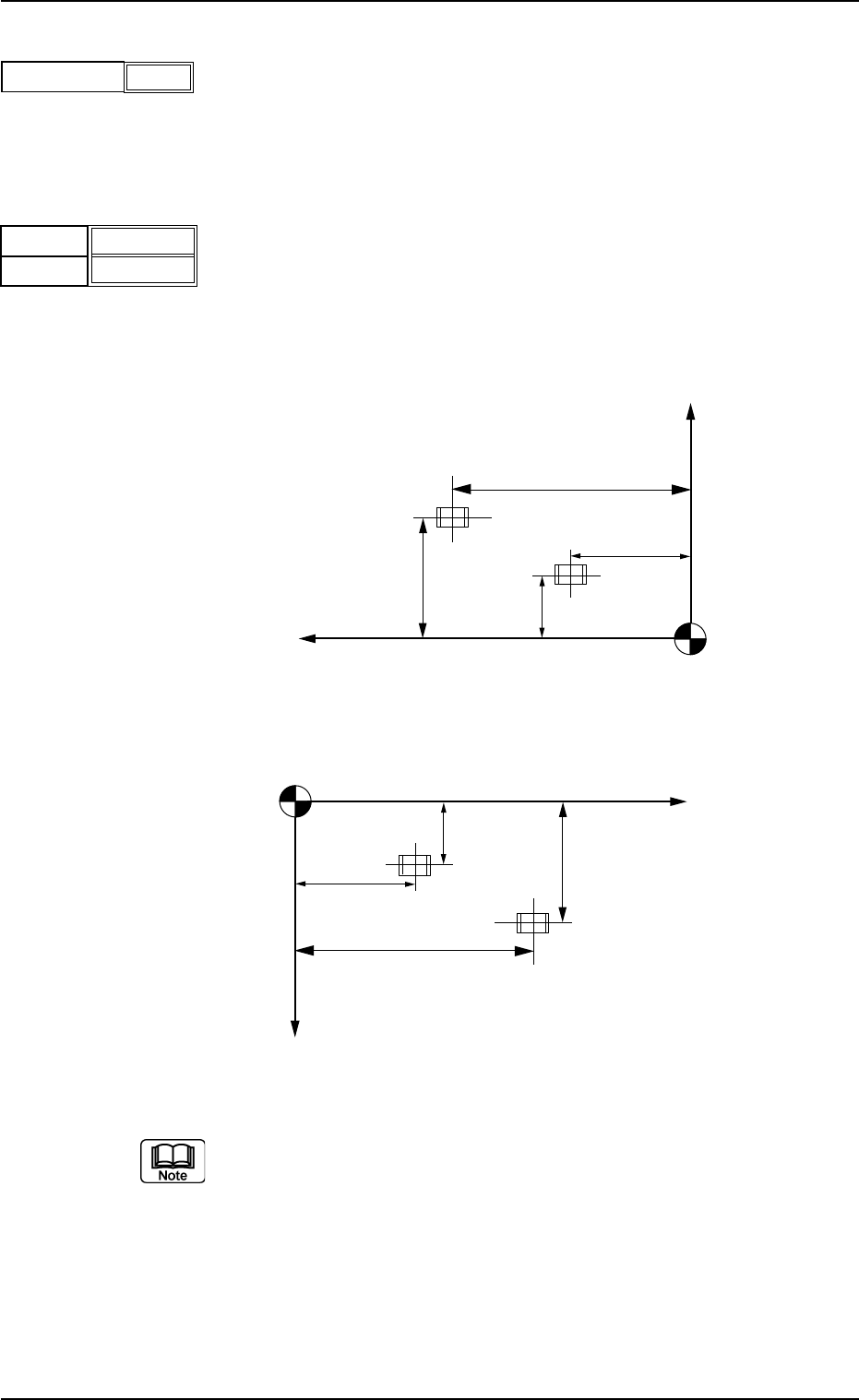
(C02_04) X [mm] and Y [mm]
Set coordinates X and Y for component placement.
The coordinates must be based on the placement coordinate refer-
ence point (N
0
).
Unit: mm
Fig. 3B97
(a) Do not set any coordinates for component placement in the last line
(last step No.).
Keep them as "000.000".
(b) To use the unit P.C.B. B.B.R. detection function, set the coordinates
of the bad mark to be put on in the "X [mm]" and "Y [mm]" text
boxes of the first step (P-No. 1).
Refer to "3.5 Repetitive Patterns (Unit P.C.B. B.B.R. Function En-
abled)" for concrete examples.
2.5 Placement Data
0210-004 2-49 AFO01EDTP
1
P-No.
Fig. 3B95
Fig. 3B96
X [mm]
Y
[mm]
010.000
010.000
Y
X
Y
2
Y1
X1
X2
Placement Coordinate Reference (N0)
Y
X
Y
2
Y1
X1
X2
Placement Coordinate Reference (N0)
TCM-X100
TCM-X200 TCM-X300
(C02_05) Z
= =
= =
= theta [deg]
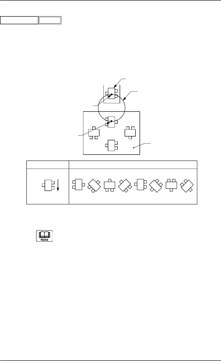
Set angles for component placement.
Unit: °(degree)
The placement angles must be determined according to the pack-
aged posture of components on the tape or the bulk feeder.
Example:
Fig. 3B99
Do not set any angle for component placement in the last line
(last P-No.).
Keep it as "+000.00".
Rotary Turret
90°
180°
270°
0°
Z
0° 45° 90° 135° 270°225°180°
315°
Packaged Posture
User Direction
of Feed
Packaged Posture of Component on
Tape Feeder
P.C.B.
Component Pick-Up Station
Component Placement Station
2.5 Placement Data
0301-005 2-50 AFO01EDTP
Fig. 3B98
+000.00
Z = theta [deg]
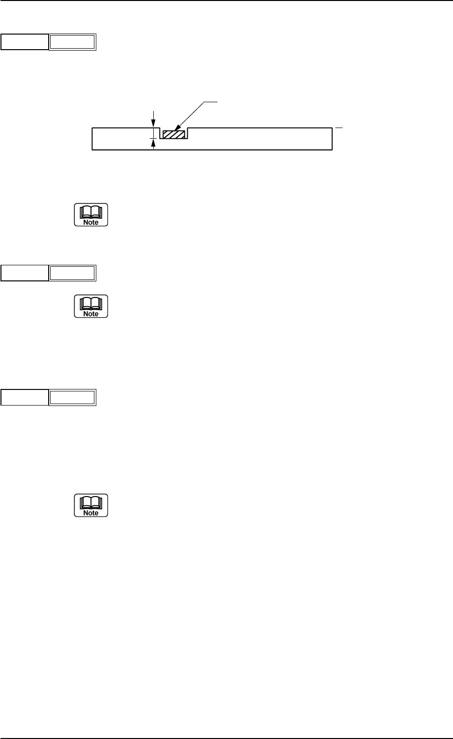
(C02_06) H [mm]
Set the height of components to be placed.
(Reserved Data)
unit: mm
Fig. 3B101
Do not set any height in the last line (last P-No.).
Keep it as "+0.000".
(C02_07) Fdr. No.
Set the Nos. of the feeders loaded with components.
(a) The feeder Nos. (Fdr Nos.) to be set here must be specified in the
placement feeder location data.
(b) Do not set any feeder No. in the last line (last step No.).
Keep it as "000".
(C02_08) V
Select one of the following options as the data for the local recogni-
tion mode.
00 : The local recognition is not performed.
01 : The local recognition (1-point recognition) is performed.
02 : The local recognition (2-point recognition) is performed.
(a) Be sure to set "Enable" in the "P.E.C. recognition mode
local" before specifying a parameter in the "V" text box.
Refer to "(A02_01) P.E.C. recognition function" in "Opera-
tion Data" for details.
(b) Refer to "(C02_11)", "(C02_12)", and "(C02_13)" for how
to specify the X and Y locations and the mark codes of the
local P.E.C. recognition mode.
P.C.B.
Component
Reference Plane
H
0301-006 2-51 AFO01EDTP
+0.000
H [mm]
Fig. 3B100
101
Fdr. No.
Fig. 3B102
2.5 Placement Data
-
V
Fig. 3B102-1