3OM-1050-002.pdf - 第220页
5 . 2 "Feeder Message Rate" T ab The corresponding tab sheet displays the pick-up rates (managed for each individual feeders) based on the feeder message rates specified in the auto operation setup data. • Shee…
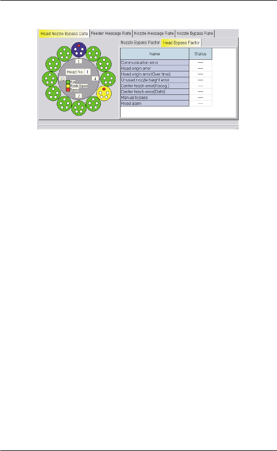
• "Head Bypass Factor" Tab Sheet
Fig. 3D21 "Head Nozzle Bypass Data" Tab Sheet
("Head Bypass Factor" Tab Sheet)
0307-005 4-43 AFO01EDTP
5.1 "Head Nozzle Bypass Data" Tab
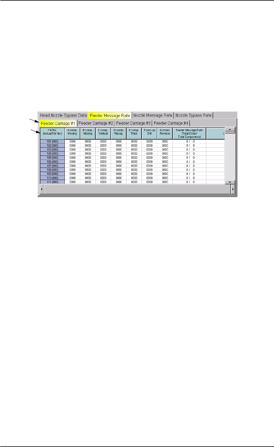
5.2 "Feeder Message Rate" Tab
The corresponding tab sheet displays the pick-up rates (managed for
each individual feeders) based on the feeder message rates specified
in the auto operation setup data.
• Sheet Layout
When the "Feeder Message Rate" tab is pressed in the "Bypass & Rate
Data" window, the following tab sheet appears inside the window.
Fig. 3D22 "Feeder Message Rate" Tab Sheet
• Sheet Composition
*1 Tabs
The "Feeder Message Rate" tab sheet is divided further into four tab
sheets and each tab sheet shows the handling errors per feeder on
each individual feeder carriage.
When a tab is pressed, the corresponding tab sheet appears, indi-
cating that the related feeder carriage is selected.
*2 Items
The following items are displayed.
(1) [Fdr No. (Actual Fdr No.)] Button
Shown are the feeder Nos.
(2) [A: comp. Missing] Button
Each text box shows the total number of missing component errors
detected by the linear measure detection sensor for each individual
feeders.
(3) [B: comp. Missing] Button
Each text box shows the total number of missing component errors
detected through recognition operation for each individual feeders.
*1
*2
0307-006 4-44 AFO01EDTP
5.2 "Feeder Message Rate" Tab

(4) [C: comp. Vertical] Button
Each text box shows the number of vertical component errors de-
tected by the linear measure detection sensor for each individual
feeders.
(5) [D: comp. Recog.] Button
Each text box shows the total number of errors detected through
recognition operation for each individual feeders.
(6) [E: comp. Thick] Button
Each text box shows the total number of errors in component thick-
ness detected by the linear measure detection sensor for each indi-
vidual feeders.
(7) [F: pick-up Diff] Button
Each text box shows the total number of pick-up difference errors
detected through recognition operation for each individual feeders.
(8) [G: Comp. Reverse] Button
Each text box shows the total number of reversed component er-
rors detected through recognition operation for each individual feed-
ers.
(9) [Feeder Message Rate (Total Errors/Total Components)] But-
ton
Each text box shows the rate of pick-up errors (the number of pick-
up errors per number of picked components) for each individual
feeders.
(10) [Component ID.] Button
Each text box shows the component ID for each individual feeders.
0307-005 4-45
AFO01EDTP
5.2 "Feeder Message Rate" Tab