3OM-1050-002.pdf - 第60页
(A04) Setup Data Fig. 3B70 Edit Window (Example) Unless "Enable" is selected for a device to be set up, the machine does not perform any setup operation on the device. (A04_01) L conveyor Set "Disable"…
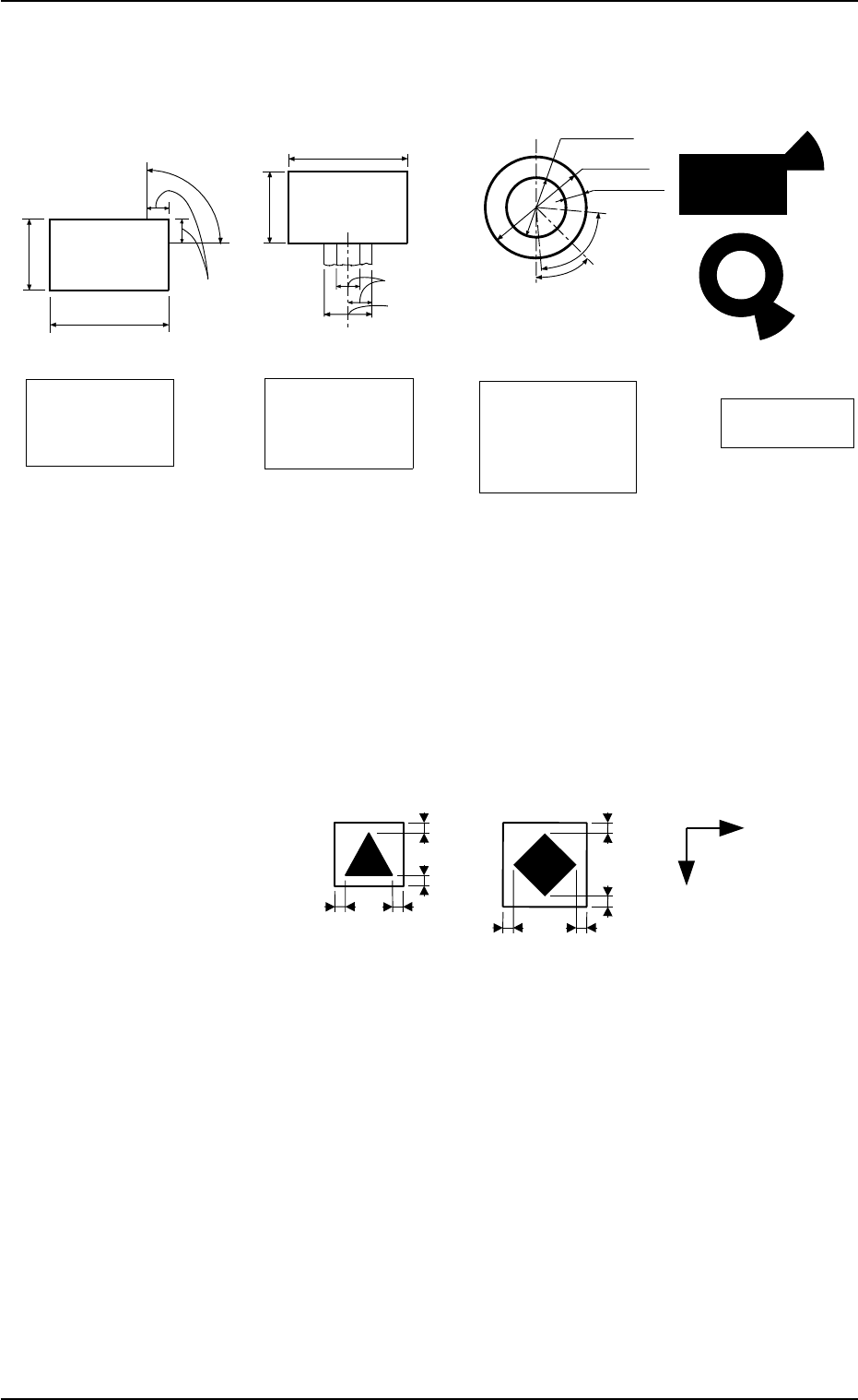
(4) Specifications of Lines extended from a Pad Mark or a Through Hole
Unit: mm
Fig. 3B68
(a) A through hole or a pad mark should have only one land
which is directed in increments of 45°.
Consult our marketing department for details such as di-
mensions, etc.
(b) A copper leaf, a resist, a coating, a silk print, and a
punched hole should not exist in the range of 1.0 mm in
both X and Y directions from the outermost edges of a
fiducial mark. They may cause false recognition.
Example:
(Front Side of Machine)
Unit: mm
Fig. 3B69
(c) The shape of P.C.B. (a cutout, a punched hole), the exter-
nal elements (light reflected from a structure, light emitted
from an external device, etc.) may sometimes interfere with
recognition of the fiducial marks. Consult our marketing
department or sales agency for details.
(d) A fiducial mark should make ample contrast with the sur-
roundings. (To prevent false recognition)
(e) Anything resembling a pattern similar to a fiducial mark
should not exist in the designated window. If one exists, it
may cause false recognition.
(f) A test may be required when the fiducial mark cannot be
recognized because of the extreme warpage of the P.C.B.
1.0
1.0
1.0
1.0
1.0
1.0
1.0
1.0
Y
X
2.3 Operation Data
0307-004 2-40 AFO01EDTP
Range of Tangent
Lines related between
Pad Mark and Land
Range of Land
Location in
Increments of 45°
for Pad Mark
Range of Land
Location in
Increments of 90°
for Pad Mark
(Front Side of Machine)
1/3 of Shorter Side
0.5 to 2.0
0.5 to 2.0
Examples of
Land Locations
Range of Land
Location for
Through Hole
(45° at the bottom
right of the hole)
0.5 to 1.5
1.0 to 2.0
Min.0.25
45°
80°
0.5 to 2.0
0.5 to 2.0
(Front Side of Machine)
(Front Side of Machine)
(Front Side of Machine)
1/3 of Shorter Side
Range of Tangent
Lines related between
Pad Mark and Land
Range of Tangent
Lines related between
Pad Mark and Land
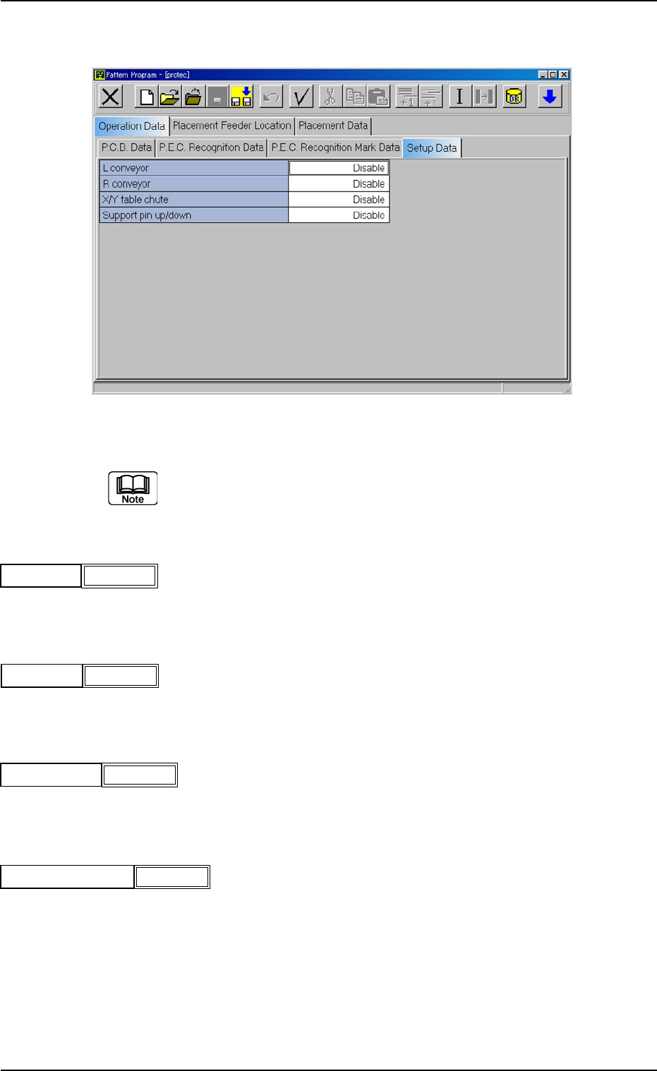
(A04) Setup Data
Fig. 3B70 Edit Window (Example)
Unless "Enable" is selected for a device to be set up, the machine does
not perform any setup operation on the device.
(A04_01) L conveyor
Set "Disable" or "Enable" in the text box.
(A04_02) R conveyor
Set "Disable" or "Enable" in the text box.
(A04_03) X/Y table chute
Set "Disable" or "Enable" in the text box.
(A04-04) Support pin up/down
Set "Disable" or "Enable" in the text box.
2.3 Operation Data
0110-003 2-41 AFO01EDTP
Disable
L conveyor
Fig. 3B71
R conveyor
Fig. 3B72
Disable
X/Y table chute
Fig. 3B73
Disable
Support pin up/down
Fig. 3B74
Disable
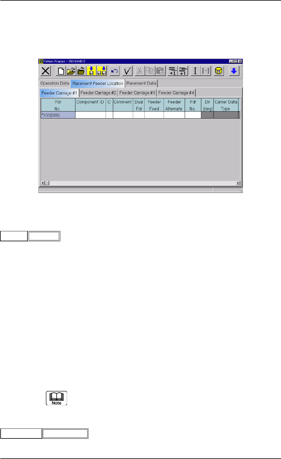
2.4 Placement Feeder Location Data
(B01) Feeder Carriage #1, #2, #3, and #4
Each parameter must be set for the feeder carriages to be used.
Fig. 3B77 Edit Window (Example)
(B01_01) Fdr No.
Shown are the feeder Nos. in the placement feeder location data.
The numbers in ( ) indicate the feeder Nos. that will actually be loaded
with components.
Data Input Range
TCM-X100 TCM-X200
Feeder Carriage #1: 101 to 179
Feeder Carriage #2: 201 to 279
Feeder Carriage #3: 301 to 379
Feeder Carriage #4: 401 to 479
TCM-X300
Feeder Carriage #1: 101 to 170
Feeder Carriage #2: 201 to 270
Feeder Carriage #3: 301 to 370
Feeder Carriage #4: 401 to 470
The numbers in ( ) indicate the feeder Nos. where the feeder No. offset in
the operation data is added.
(B01_02) Component ID
Set component IDs in the text boxes.
2.4 Placement Feeder Location Data
0301-005 2-42 AFO01EDTP
101(101)Fdr No.
Fig. 3B78
C1005T05B0---
Component ID
Fig. 3B79