N7201A652E.pdf - 第161页
NPM- TT2 EJM1EE-MB -02O-04 2-5-3 -4 10 Attach the PCB support block as th ere is no tilt (A void interfe ring with the rail) ● Adjust the guide pins on the main unit to the holes on the PCB support block. Guide pin Remov…

NPM-TT2 EJM1EE-MB-02O-04
ACTIVATION
ACTIVATION
2-5-3-3
9
Insert support pins to the PCB support block
●Install the support pins as entire PCB is evenly supported.
●Be careful not to bump pins against the components on the
reverse side of PCB.
●Using the support pin set jig (option) can prevent support pins
from inserting in wrong positions.
(Jig: N610131762AD)
Individu-
al
prepara-
tion
Operating procedure
2-5-3
14
SERVO
ON
15
16
17
●The PCB support block
lowers
Attach the tray
feeder or the feeder
cart
●For a tray feeder
(→[Maintenance] P.14-8)
●For a feeder cart
(→[Maintenance] P.3-2)
●Only for the exchange cart
Setting support pins 2
NPM-TT2 EJM1EE-MB-02O-04
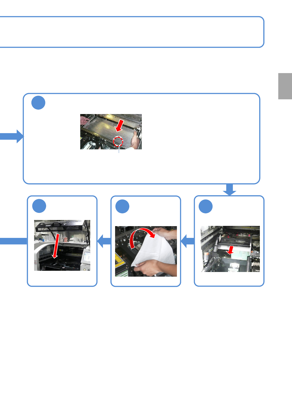
2-5-3-4
10
Attach the PCB support block as there is no tilt (Avoid interfering with the
rail)
●Adjust the guide pins on the main unit to
the holes on the PCB support block.
Guide pin
Remove the
cloth
12 11
13
Put the feeder
table cover back
in its place
●Only for the exchange cart ●Only for the exchange cart
Preparation
NPM-TT2 EJM1EE-MB-02O-04
2-5-4
Individu-
al
prepara-
tion
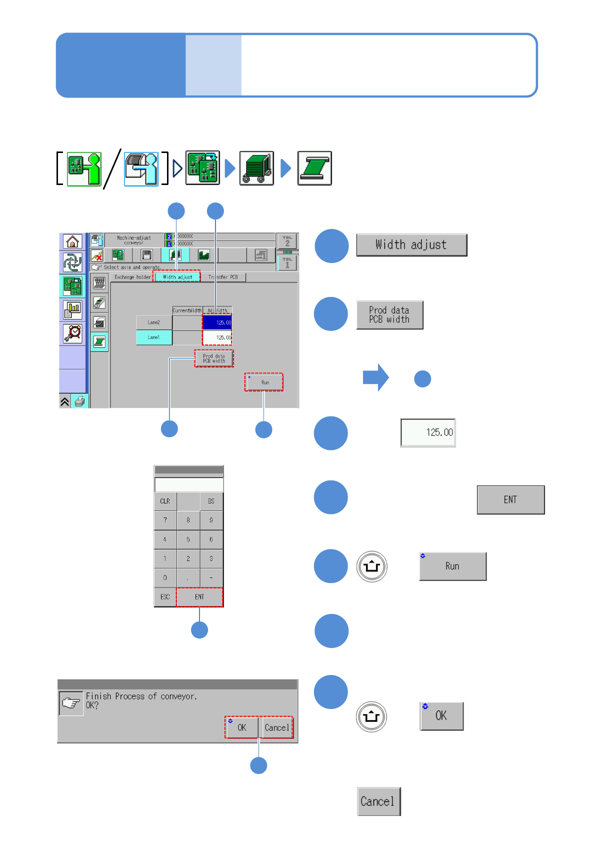
Adjusting transport
conveyor width
This explains how to adjust the transport conveyor width.
●When you change to smaller PCBs, remove the PCB support blocks and the support pins.
2
5
1
1
2
4
+
(The transport rail width is adjusted)
■To adjust to the PCB width of
production data
■To enter a new PCB width
(The numeric keypad window appears)
Type a PCB width
5
6
Press the next operation button
7
Confirm the message
+
(Switches to the next operation screen)
Touch
5
3
3
7
■To cancel
4
Operating procedure
2-5-4
To
(The PCB width of production data is
shown in the numerical field of ‘AdjWidth’)