N7201A652E.pdf - 第164页
NPM- TT2 EJM1EE-MB-02 O-04 2 1 Specify a target for placement 1 3 (Production starts under the specified conditions) ■ To specify by the pattern ■ To specify by the placement point ■ To specify by the componen t (intelli…
NPM-TT2 EJM1EE-MB-02O-04
Individu-
al
prepara-
tion
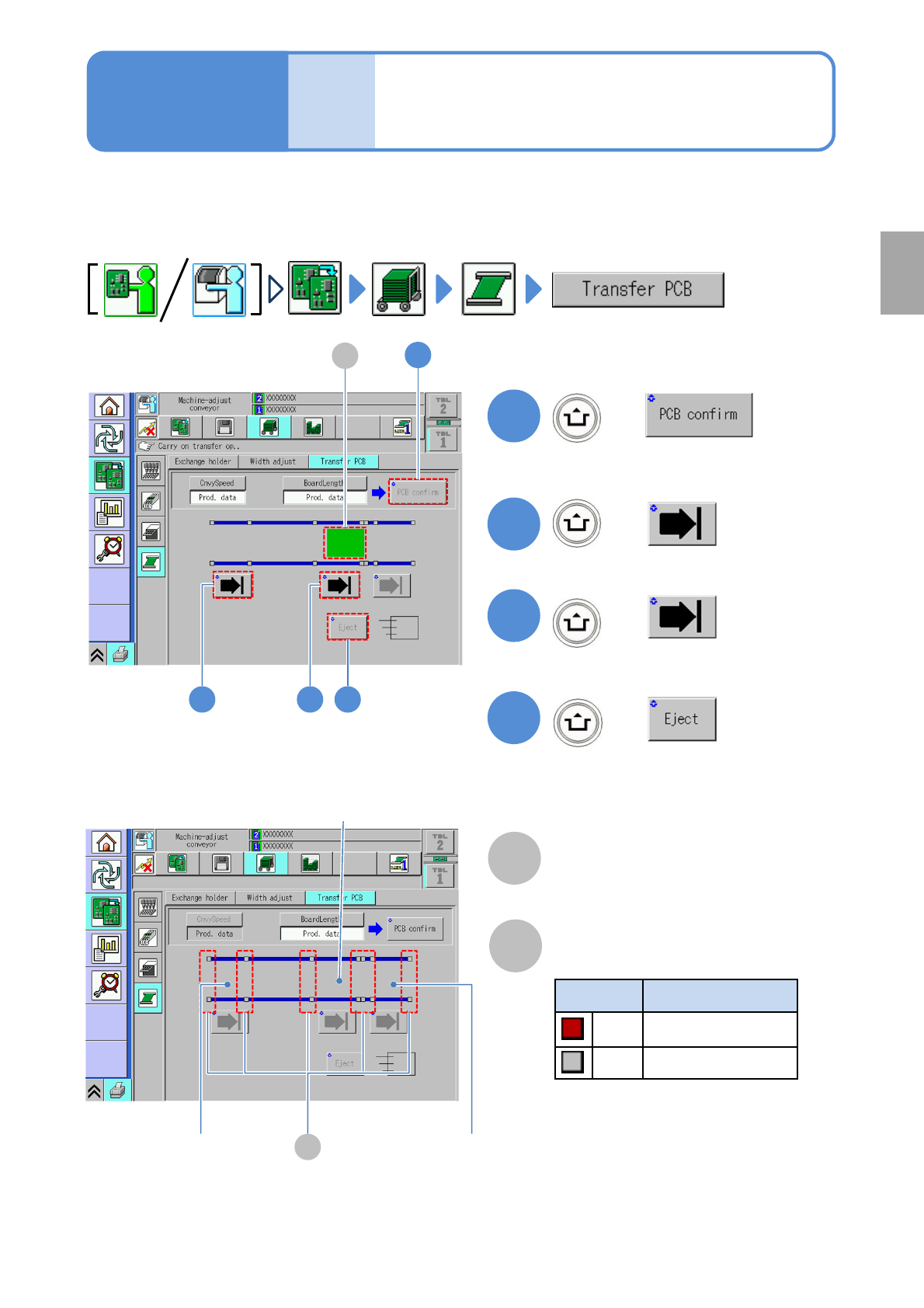
PCB transport test
This explains how to test PCB transport on the assumption that you have completed testing on the
preceding processes and that PCBs are present in the upstream process.
●For dual conveyor, you need to choose a lane in advance.
2-5-5
B
Sensor
Color Sensor status
*1)
Red ON
Gray OFF
A
PCB transfer position
The location of PCBs on the transport
conveyor is displayed.
2
3
+
+
4
+
(Transported to the loading position)
(Transported to the placement position)
(Unloaded to the next machine)
2 3 4
1
1
+
A
*1) This sensor shows the presence /
absence of PCB, with the support
plate being lowered.
Operating procedure
2-5-5
B
Loading position Unloading position
Placement position
Preparation
(Confirm PCB presence and put it in
transfer ready condition)
NPM-TT2 EJM1EE-MB-02O-04
2
1
Specify a target for placement
1
3
(Production starts under the specified
conditions)
■To specify by the pattern
■To specify by the placement point
■To specify by the component
(intelligent feeder)
■To specify by the component
(tray feeder)
■To specify by the head
■To cancel selection
(→P.2-5-6-2)
(→P.2-5-6
-3)
(→P.2-5-6
-4)
(→P.2-5-6
-5)
(→P.2-5-6
-6)
(→P.2-5-6
-6)
2-5-6-1
2
Individu-
al
prepara-
tion
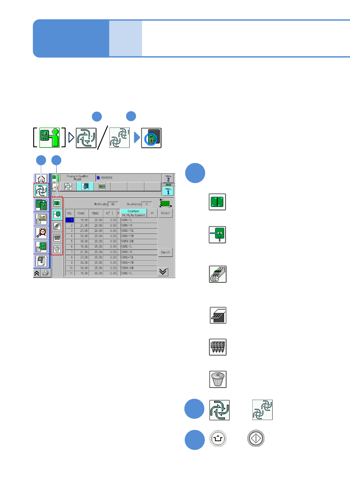
Placement specification 1
(conditional placement)
Operating procedure
2-5-6
or
Preparation: do steps through in P.3-1-1-1,P.3-1-1-2.
1
4
A target for placement is specified for production in the unit of patterns or placement points.
Before starting production, using a particular component or block, run a trial to check the placement condition.
For a placement check based on conditional placement, perform the following steps.
For dual conveyor, you can set it per lane by changing the lane.
Inspection head-equipped equipment does not support solder and component inspections during the conditional
placement process.
+
NPM-TT2 EJM1EE-MB-02O-04
2
1
1 2
Select a pattern
●Multiple patterns are selectable.
3
3
●Deselected by pressing the button
again.
E FC D I
2-5-6-2
A
E
F
G
B
C
D
I
J
H
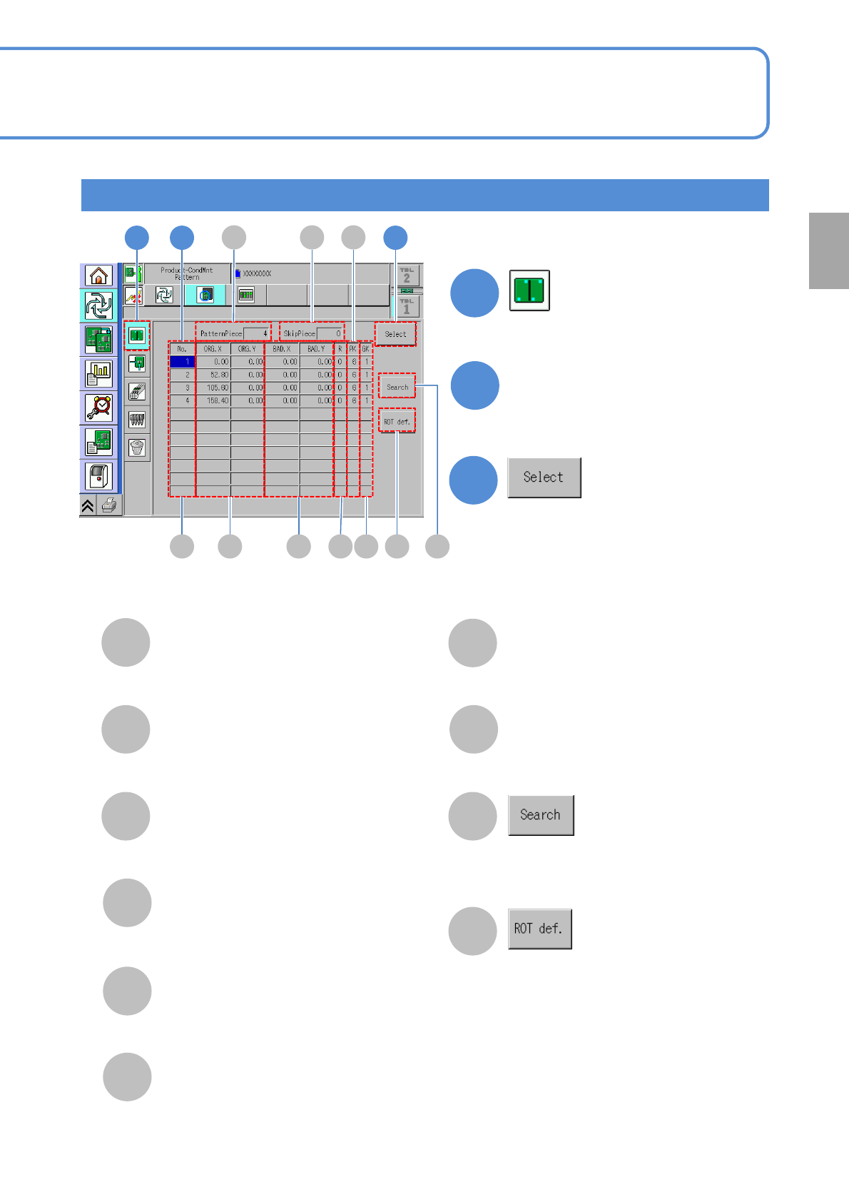
PatternPiece
The total number of patterns.
SkipPiece
The total number of specified
patterns to be skipped.
No.
The pattern ID number.
ORG.X/ORG.Y
The X/Y coordinates of the origin
pattern.
BAD.X/BAD.Y
The X/Y coordinates of bad patterns.
R
The pattern developing angle
number.
PK
The pattern number.
H
Run search by entering a pattern
number with the numeric keypad.
Displays the ROT definition window.
GK
The group number.
Specify by the pattern
J
A GB
Preparation