N7201A652E.pdf - 第62页
NPM- TT2 EJM1EE-SF-01N-05 Com- ponent names A ppear ance dia g r am/Oper ating units Front side Rear side Appearance diagram 1-9-1 -1 1-9-1 Component empty lamp Automatic run Outlet Inlet Outlet Inlet Light OFF: Normal r…
NPM-TT2 EJM1EE-SF-01N-05
Safety dispose of the linear motor after fully understanding the following matters.
TO THE WASTE
DISPOSAL EXPERT
1. Procedures for removing and disposal of the linear motor
1) To prevent fire, remove combustible materials, such as plastic parts or wirings, near the linear motor
before you apply heat to the linear motor.
2) Demagnetize the linear motor.
Evenly apply heat to the surface of the linear motor’s stator (permanent magnet) with an acetylene gas
burner for more than five minutes, with the surface temperature kept at approximately 1,000°C.
Confirm that the magnetic force is reduced.
3) Confirm that the magnetic force is 10 mT or less, or check to see whether the steel scale is not strongly
attracted.
4) After confirming that it has been demagnetized, dispose of it as industrial waste.
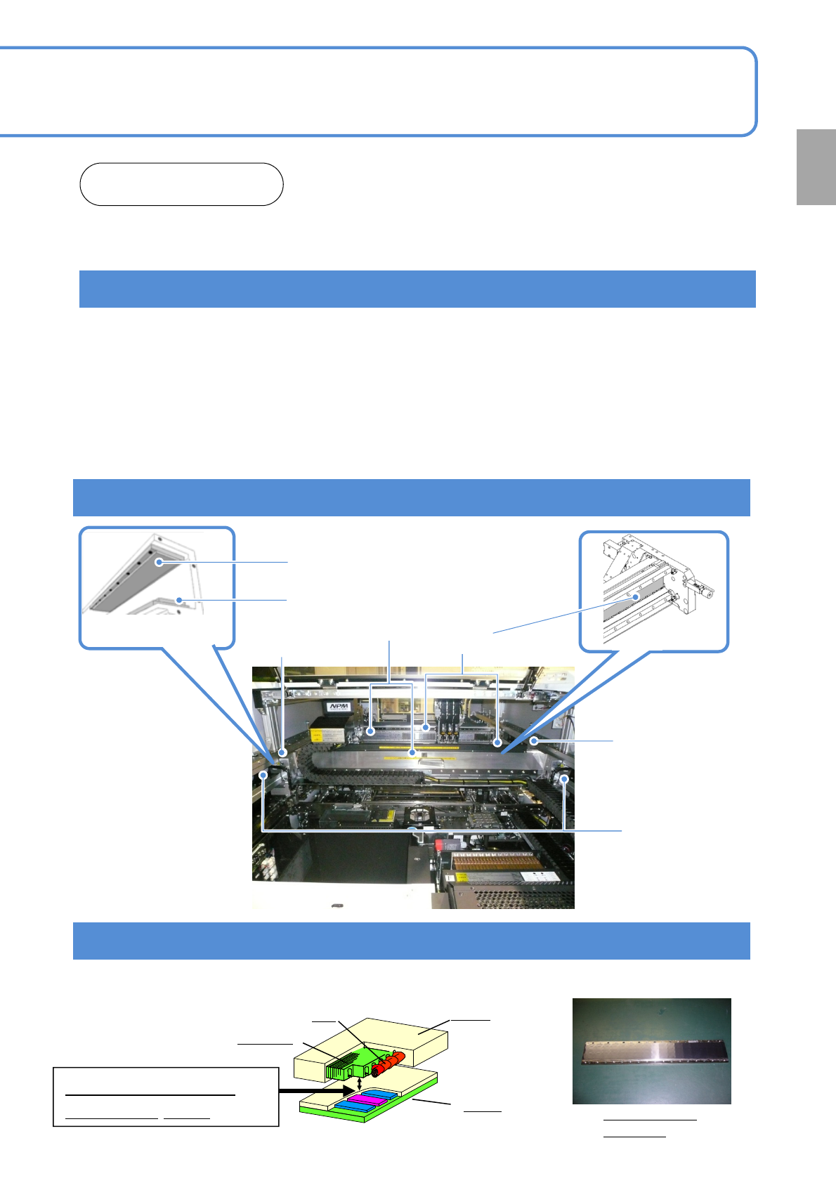
2. Where the linear motor is used
Y-axis linear motor
X-axis stator (magnet)
Y-axis stator (magnet)
X-axis linear motor
Y-axis stator (magnet)
Y-axis upper stator (magnet)
Y-axis lower stator (magnet)
1-8-2
[REFERENCE] Structure and high magnetic force of the linear motor
Understand the structure of the linear motor to prevent an accident. The structure may differ slightly from one
model to another, but basically it is the same in each model.
Stator
Sample picture
of a stator
Mover
Coil
Iron core
Maximum magnetic
force of 10,000N
Confirmation
NPM-TT2 EJM1EE-SF-01N-05
Com-
ponent
names
Appearance
diagram/Operating units
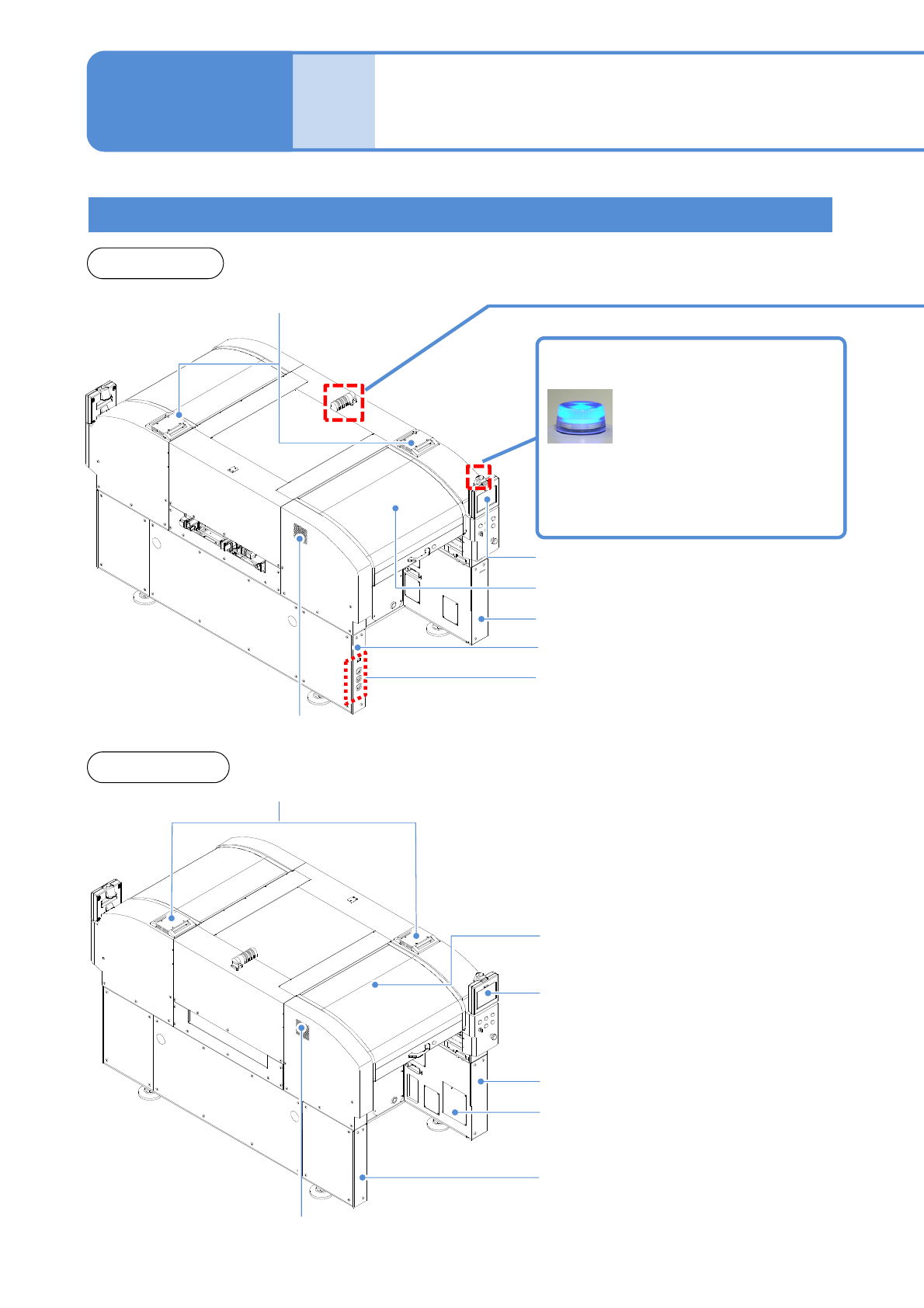
Front side
Rear side
Appearance diagram
1-9-1-1
1-9-1
Component empty lamp
Automatic run
Outlet
Inlet
Outlet
Inlet
Light OFF: Normal run
Light ON: Components have
run out
Flashing: Shortage of component
Safety cover (Front side)
Touchscreen (Front side)
Safety cover (Rear side)
Touchscreen (Rear side)
Regulator cover (Rear side)
Various pressure gauges
Regulator cover (Front side)
Cover (Front side)
Cover (Rear side)
Power supply cover (Rear side)
NPM-TT2 EJM1EE-SF-01N-05
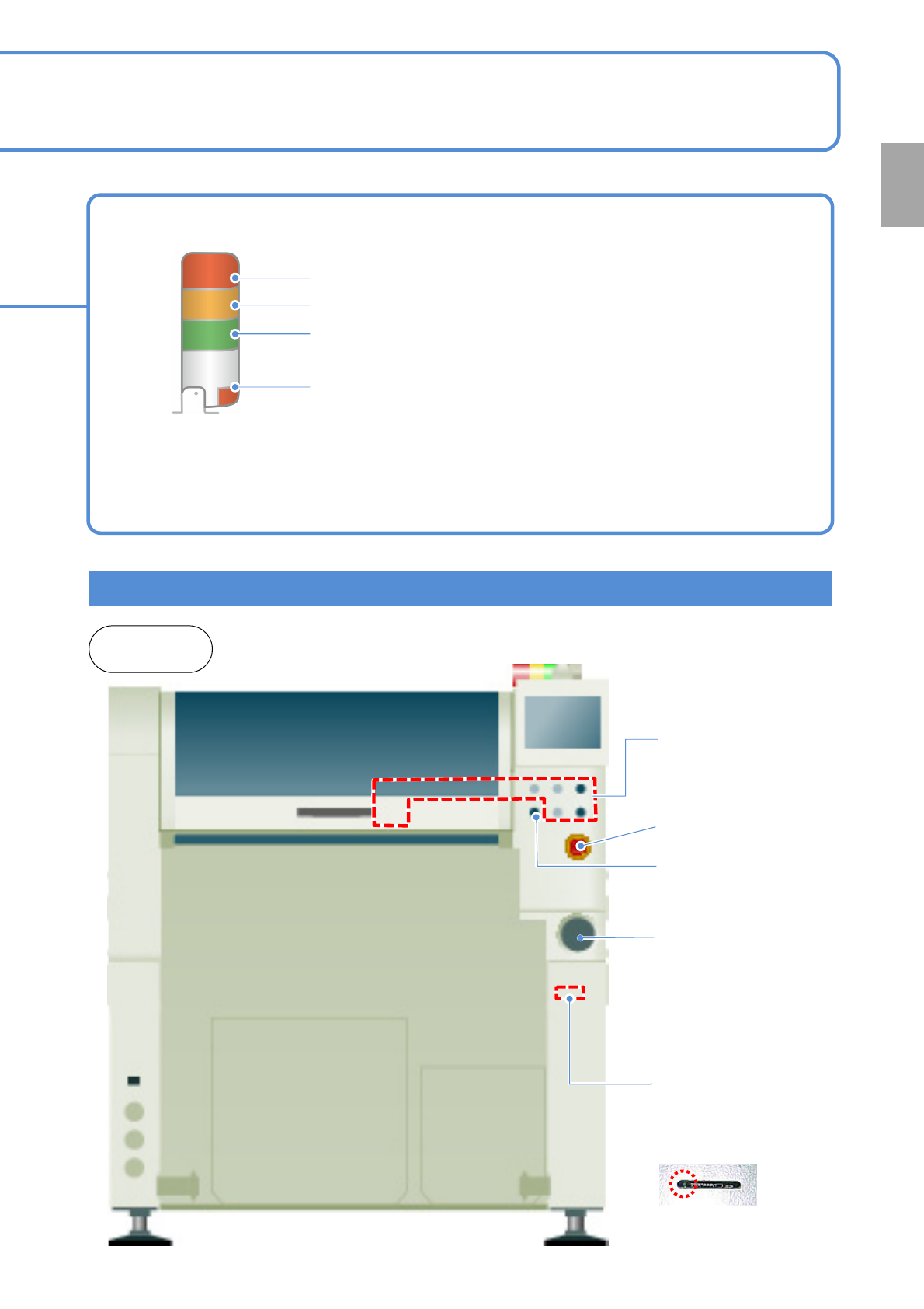
Operating units
Emergency stop
switch
Stops operation
immediately
Main power supply
switch (Front side)
Turns ON/OFF the power and
air source.(When you turn off
the power supply switch, the
air supply is shut off also.)
1-9-1-2
Signal tower
Red: Illuminates when you push emergency stop switch or in case
of error stop.
Yellow: Illuminates in case of material shortage.
Green: Illuminates in automatic operation.
Red: Illuminates when you push emergency stop switch or in case
of error stop.
● You can change the above setting.
[Operating Procedure] (→ P.5-1-3)
● Please refer to the [Operating Procedure] (→P.5-2-4)
●The signal tower is placed sideways when shipped , however the angle can be adjusted.
Front and
rear sides
Various operation
switches
Controls operation start /
stop.
Access lamp
(Green LED)
SD card reader
(Front side)
Reading and writing of
programming data.
Servo switch
Turns ON/OFF the
power of servo units.
Confirmation