N7201A652E.pdf - 第455页
NPM- TT2 EJM1E E-MB-05O-05 5-3-2 Machine parame- ter Placement position of fset c hec k Operating procedure 5-3-2 System administration You can check placement position offset. Line camera, 3D sensor X[mm]/Y[mm]/ θ [ ° ]…
NPM-TT2 EJM1EE-MB-05O-05
5-3-1
Machine
parame-
ter
XY origin offset/XY
standard mark check
A
B
設備に設置されているフィーダーのメモリー情報を表示します。
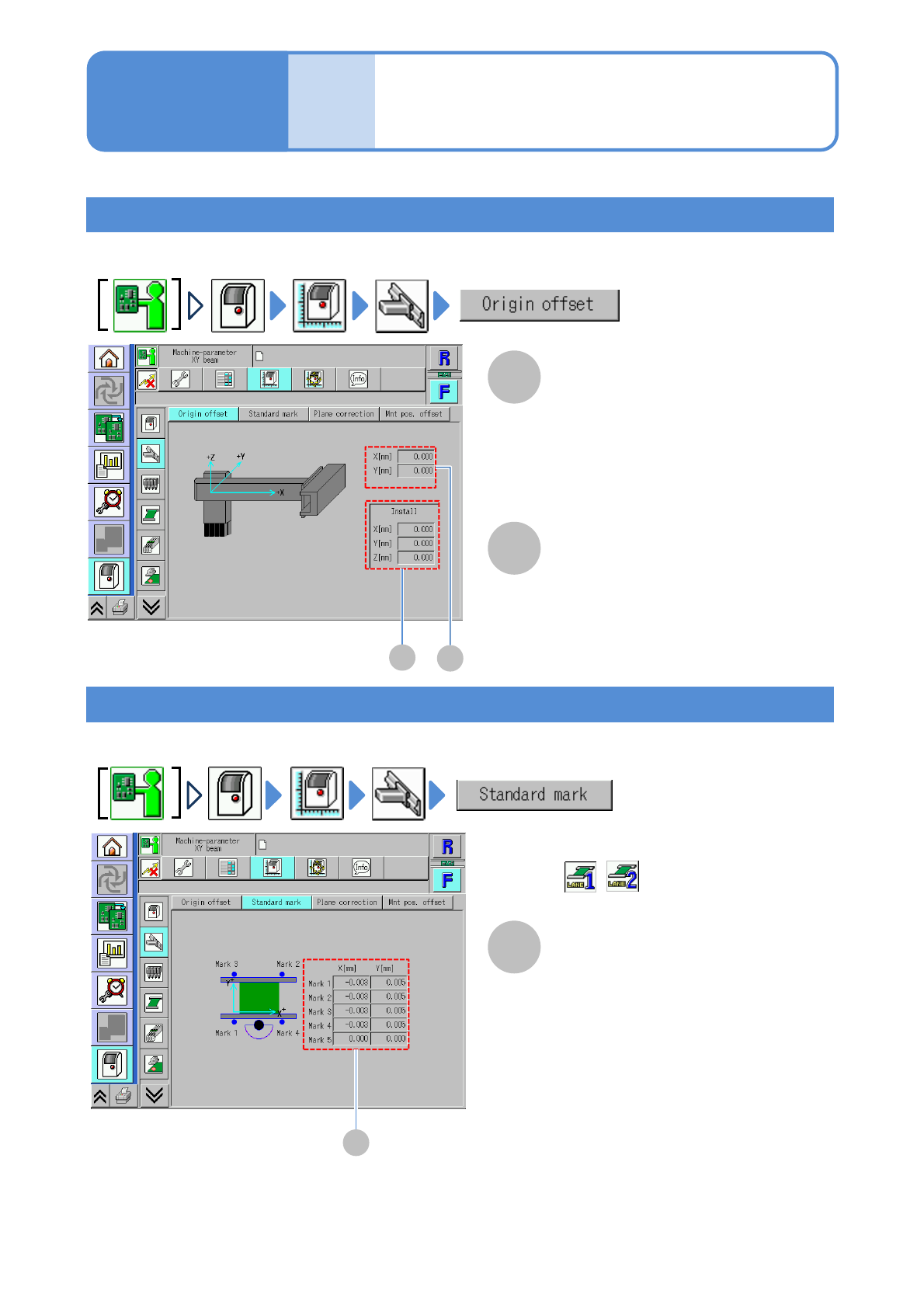
XY origin offset
You can check the origin offset values (calibration result) of X-/Y-axes.
XY standard mark
You can check the offset value (calibration result) to move the head to the XY standard mark position.
●For dual conveyor, you need to choose a lane in advance.
B
A
A
A
Operating procedure
5-3-1
Origin offset X[mm]/Y[mm]
The criterion for X-/Y-axes actions and
the origin offset value of each axis.
Install X[mm]/Y[mm]/Z[mm]
The criterion for X-/Y-axis actions that is
used in installing the head, and the
origin offset value of each axis.
Standard mark coordinates
X[mm]/Y[mm]
XY coordinate offset of the standard
mark of the transfer conveyor.
■For dual conveyor
(Select a lane in advance)
NPM-TT2 EJM1EE-MB-05O-05
5-3-2
Machine
parame-
ter
Placement position
offset check
Operating procedure
5-3-2
System
administration
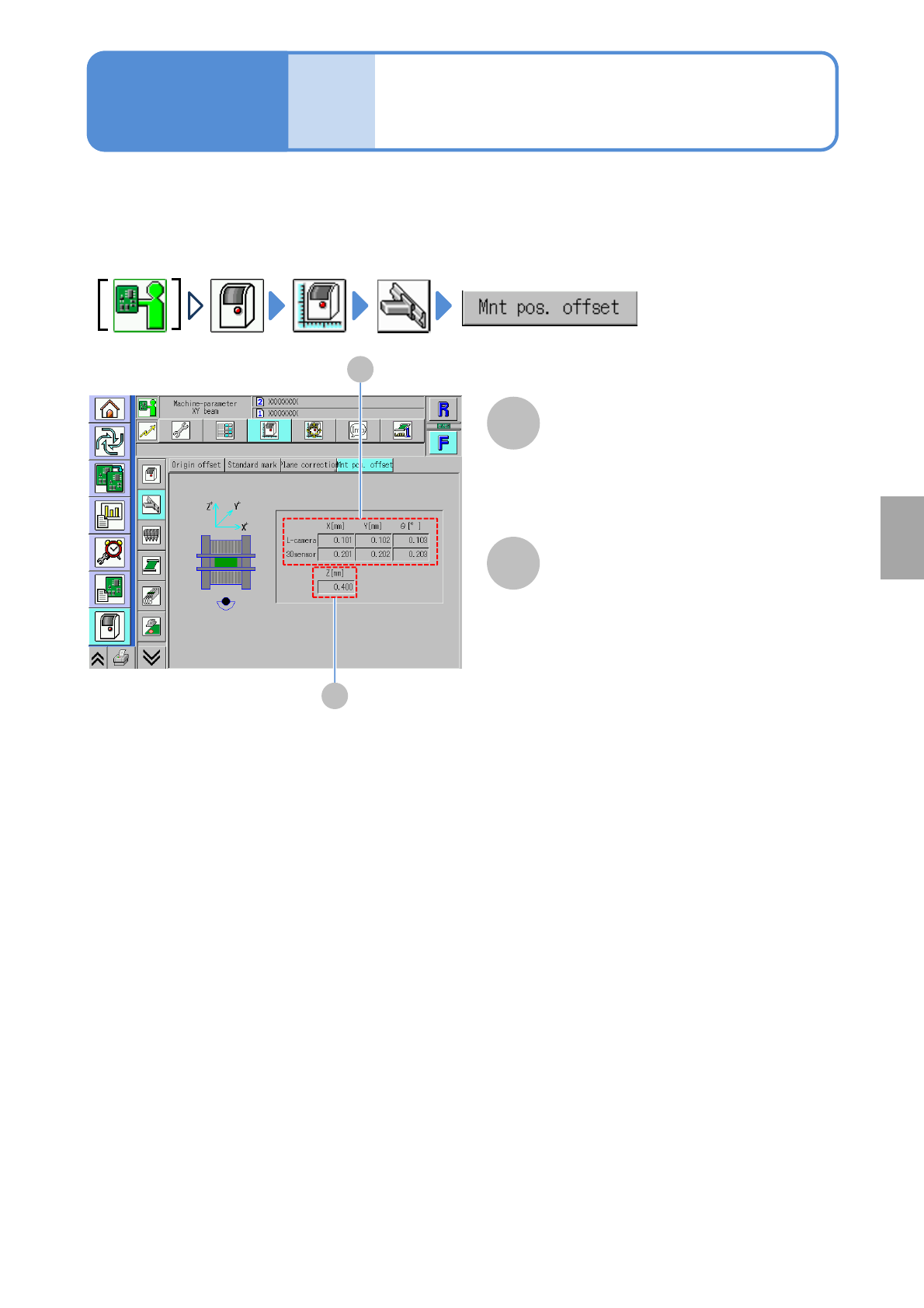
You can check placement position offset.
Line camera, 3D sensor
X[mm]/Y[mm]/ θ[°]
Displays X-, Y- and θ-coordinates
corresponding to the line camera and the
3D sensor on the placement position
offset.
A
B
B
A
Z [mm]
Displays Z-coordinate on the
placement position offset.
NPM-TT2 EJM1EE-MB-05O-05
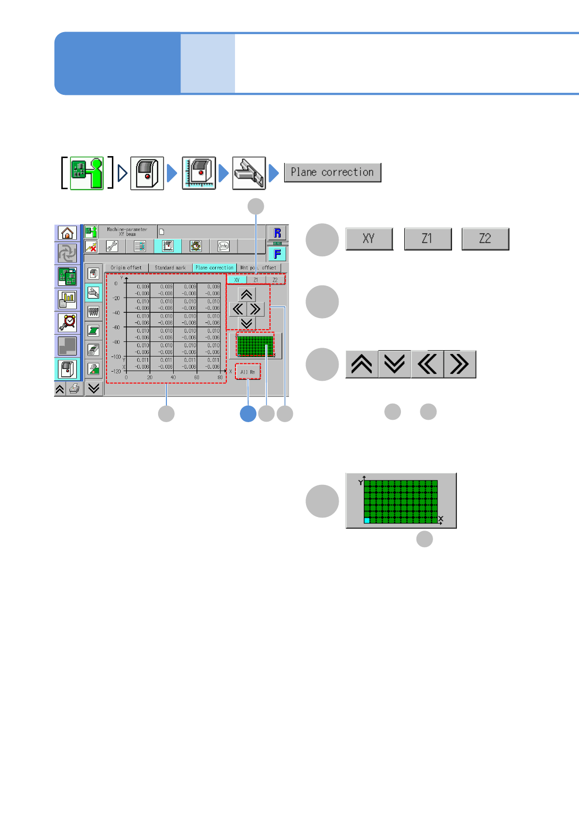
Display area of is displayed in light
blue color.
The front/rear/right/left of the display
areas of and are displayed.
You can check the placement surface offset (calibration result) used in correcting PCB recognition and
placement positions.
5-3-3-1
Machine
parame-
ter
XY/Z plane correction
check
A
C
C
B
A
B 4
//
D
D
B D
B
Operating procedure
5-3-3
Switches between offset displays.
Offset
Placement surface offset.
●Displayed at intervals of 20 mm.