N7201A652E.pdf - 第433页
NPM- TT2 EJM1E E-MB-05O-05 5-2-5 -6 Install/Remove of a nozzle + + ■ To attach nozzles ■ To remove nozzles (The nozzle for support pins is installed to the head) (The no zzle for suppor t pins is removed fr om the nozzle…
NPM-TT2 EJM1EE-MB-05O-05
Unit
adjust-
ment
Replacing the nozzle of
the placement head 3
5-2-5-5
Operating procedure
5-2-5
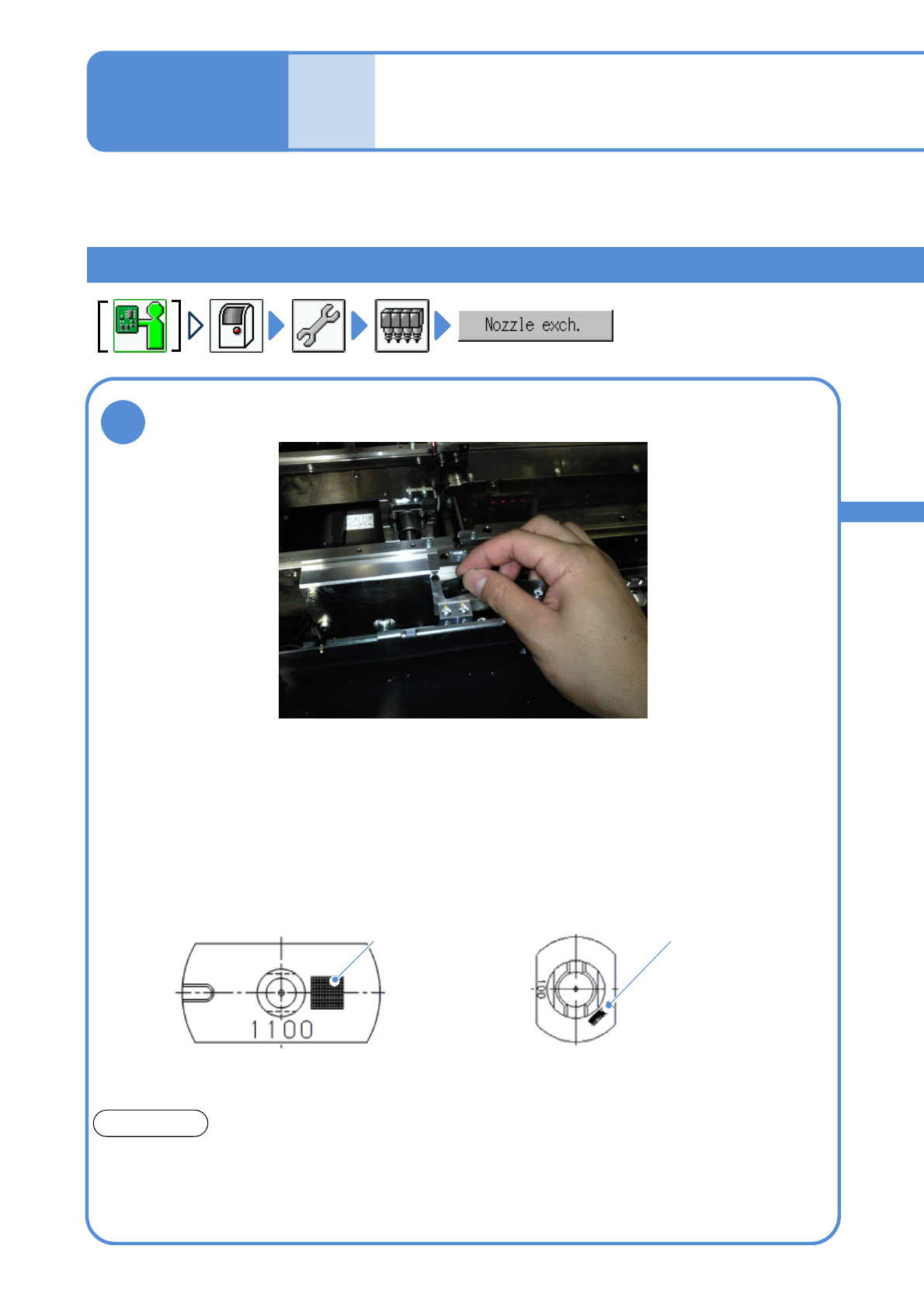
Installing a nozzle for support pins
1
●In the case of a nozzle for 3-nozzle
head, be careful of the groove
location.
Feeder table side
●A nozzle for 8-nozzle head with 2D code is marked, place it as
an orientation shown in the figure below.
●Using an optional setting, you can avoid wrong installation in
order to detect the nozzle type by 2D code.
Feeder table side
2D code
Nozzle for support pins
ATTENTION
The shape differs from a nozzle for component pickup.
Please install the nozzle for support pins to the nozzle change r for support pins and the nozzle for
component pickup to the one for component pickup.
If you wrongly installed, shaft of the head unit may be damaged.
Describes how to place a nozzle for support pins to a nozzle change for support pins and install it to the
placement head.
Place a nozzle for support pins to the nozzle changer for support pins
100 nozzle
(for 8-nozzle head)
1100 nozzle
(for 3-nozzle head)
2D code
NPM-TT2 EJM1EE-MB-05O-05
5-2-5-6
Install/Remove of a nozzle
+
+
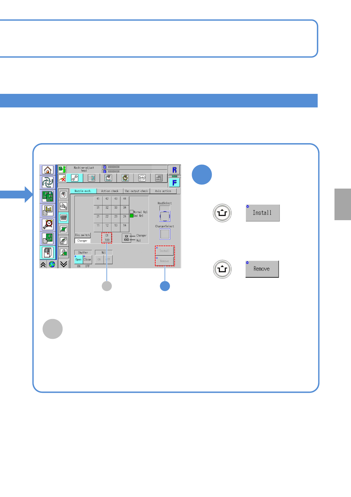
■To attach nozzles
■To remove nozzles
(The nozzle for support pins is
installed to the head)
(The nozzle for support pins is
removed from the nozzle changer
for support pins)
2A
2
A
Nozzle changer for support pins
It displays for support pin automatic change
function specification. If you install or
remove the nozzle for support pins, choose
this.
System
administration
NPM-TT2 EJM1EE-MB-05O-05
Unit
adjust-
ment
Action check of the
placement head
5-2-6-1
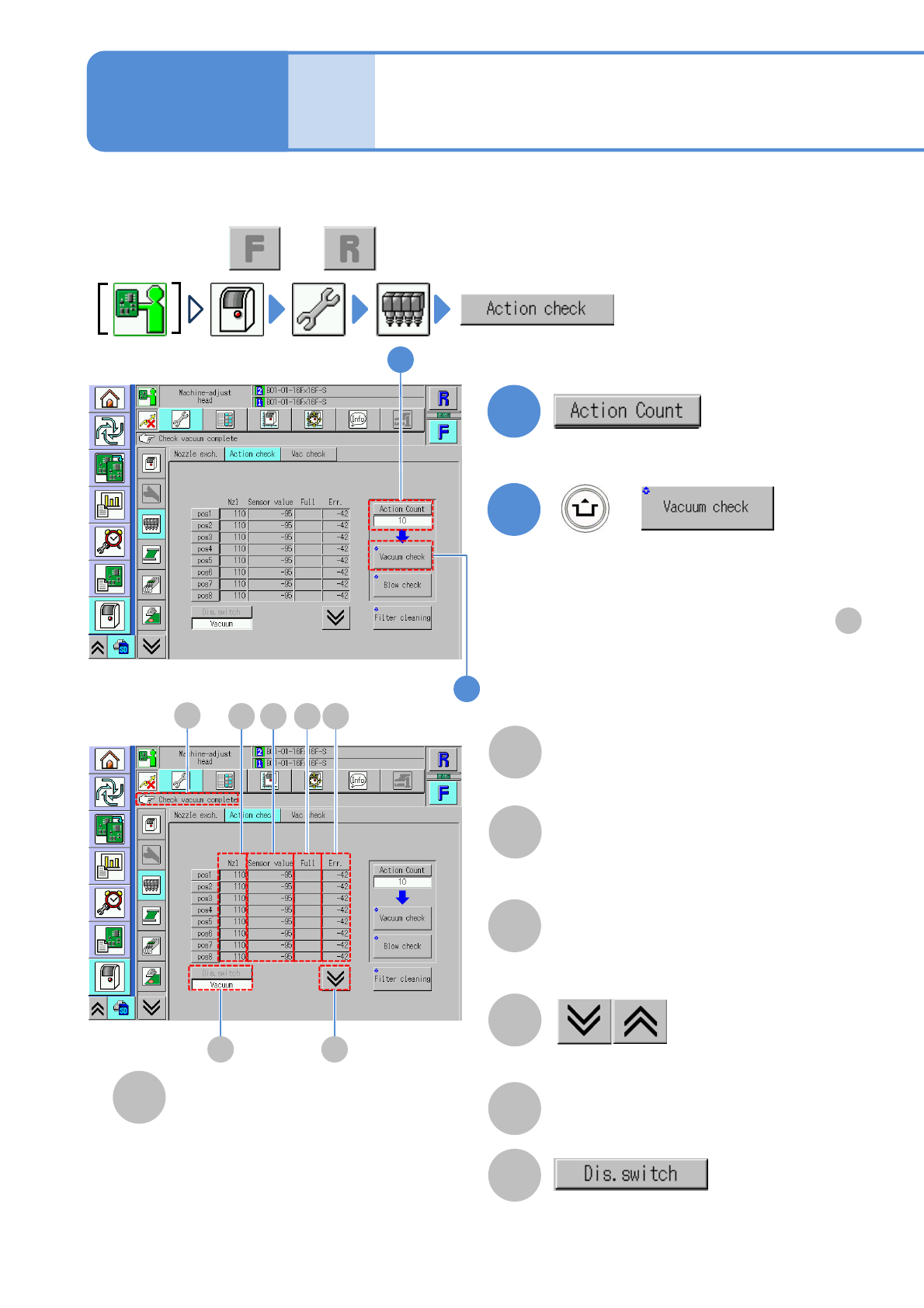
You can collectively check whether the actions of the placement head or nozzles are normal.
Operating procedure
5-2-6
1
+
A
B
C
D
E
F
(The vacuum check result of each nozzle
is displayed)
Nozzle
A number of a nozzle attached to the
placement head.
●”-” is displayed if any nozzle is not
attached.
Sensor value
●If the measured value is abnormal, its
background is shown in yellow.
Full
●Filter clogging detection value. Check
if the measured value is abnormal as
the result of [Filter cleaning].
The previous or next table is displayed.
Err.
●Nozzle clogging detection value. Check if
the measured value is abnormal as the
result of [Vacuum check].
Message display area
●Perform on both and .
C D
E
F
A B
G
1
2
■If vacuum check has completed successfully
[Check vacuum complete] is displayed in .
F
■If vacuum check failed to complete
successfully
The background of the measured value of the
corresponding nozzle is displayed in yellow.
2
G
●Change the action count (1 or 10).
Change the display of the measured
result.
●It is effective when more than two
measured results exist.