N7201A652E.pdf - 第171页
NPM- TT2 EJM1EE-MB -02O-04 2-5-7 -2 8 Detach the PCB support block (for automatic change) Removal lever ● Draw out the PCB support bloc k (for automatic change). ● Draw it out slowly with both han ds. ● Be carefu l not t…
NPM-TT2 EJM1EE-MB-02O-04
ACTIVATION
ACTIVATION
2-5-7-1
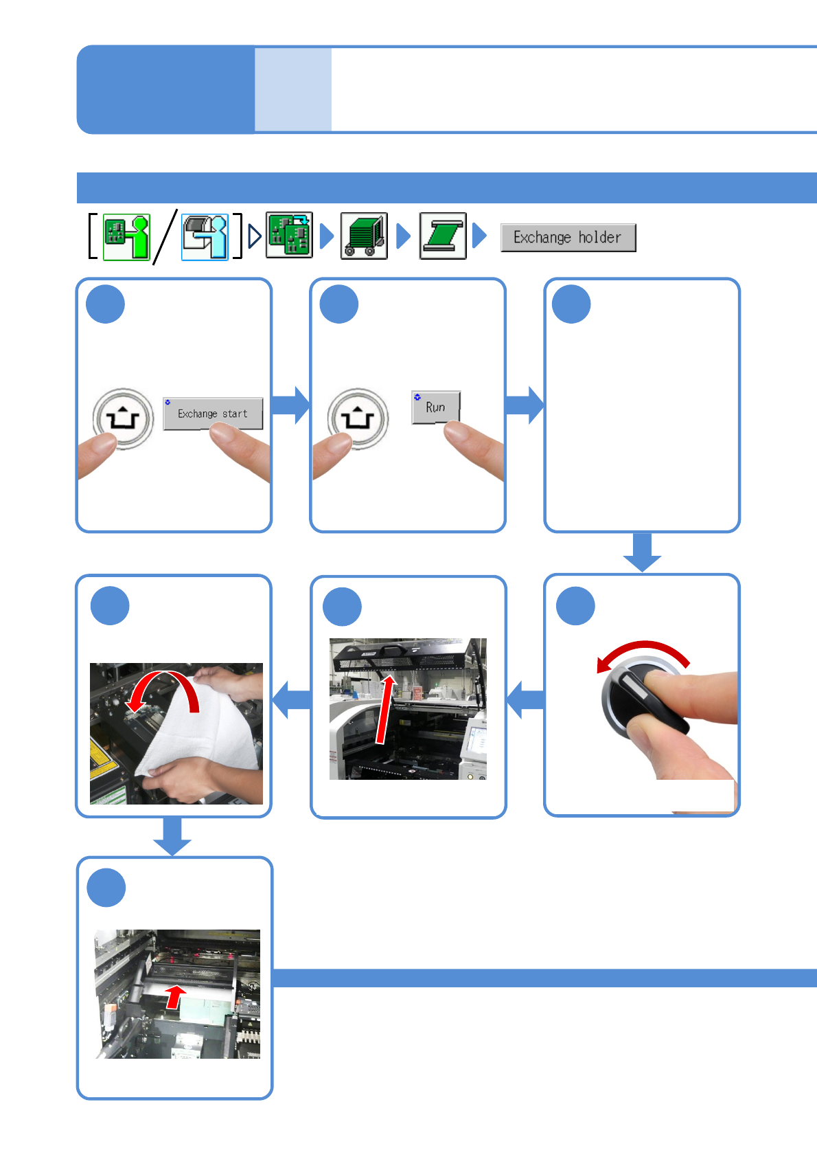
1
After removing
PCBs
2 3
Cover the line
camera with the
lint-free cloth
Individu-
al
prepara-
tion
Installing support pins (for
automatic change) 1
Operating procedure
2-5-7
Installing the support pin (for automatic change) 1
●The PCB support block
raises.
Detach the tray
feeder or the feeder
cart
●For a tray feeder
(→[Maintenance] P.14-8)
●For a feeder cart
(→[Maintenance] P.3-2)
OFF
SERVO
5
4
7
6
Fold the feeder
table cover to
the back
●Only for the exchange cart
●Only for the exchange cart
●Only for the exchange cart
NPM-TT2 EJM1EE-MB-02O-04
2-5-7-2
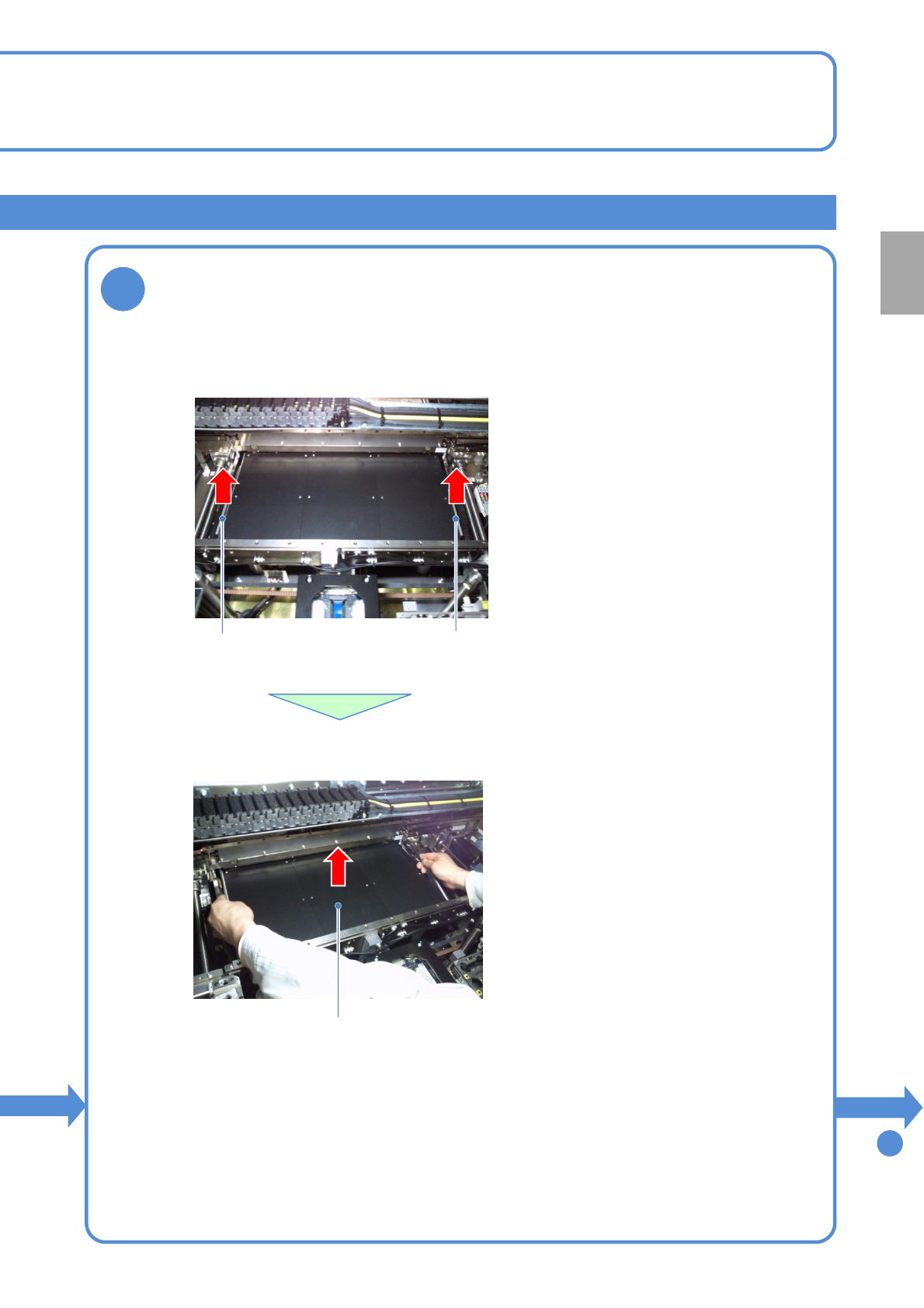
8
Detach the PCB support block (for automatic change)
Removal lever
●Draw out the PCB support block (for automatic change).
●Draw it out slowly with both hands.
●Be careful not to drop a foreign body on
the line camera (LED lighting) or bump it.
●Remove both lane as the same way.
●Lift up the right and left levers in the front.
Removal lever
To
9
PCB support block
(for automatic change)
Preparation
NPM-TT2 EJM1EE-MB-02O-04
2-5-7-3
Individu-
al
prepara-
tion
Installing support pins (for
automatic change) 2
Operating procedure
2-5-7
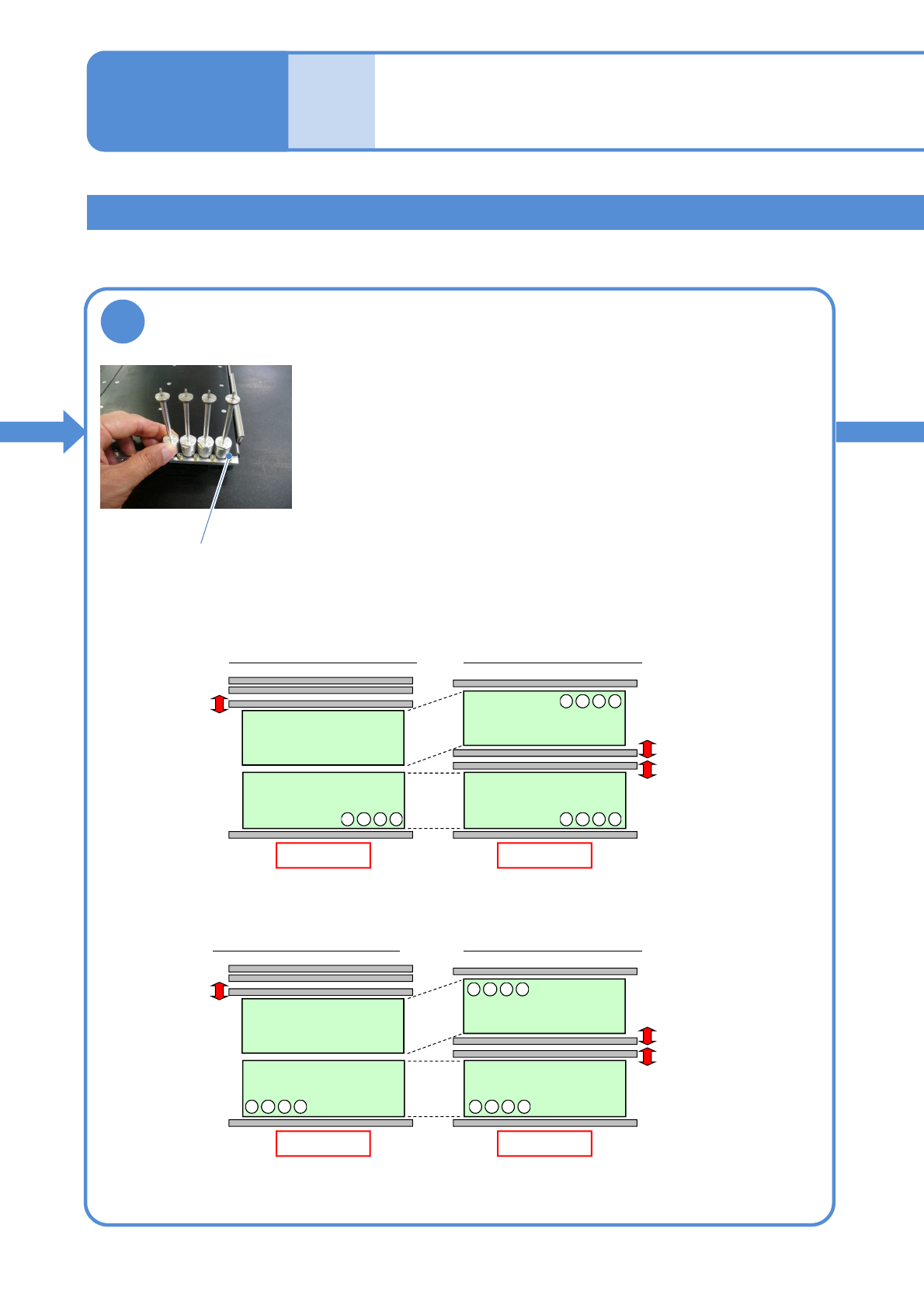
9
Set the support pins (for automatic change) to
the PCB support block (for automatic change)
●When the support pins are set, be sure to set to the home
position. (Avoid interfering with the conveyor)
● Place support pins with pushing Bolts on the hole position.
(They may interfere with vacuumed support pins during
arrangement of the pins)
●If a PCB flow is from right to left, place pins from the left end in
order. If it is reverse flow, place pins from the right end.
●For single lane mode, set pins only on the fixed rail side.
From left to right
Rear
Front
Arrangement on single lane mode
Front
Lane 2
Lane 1
Arrangement on dual lane mode
Front
4321
・・・
4321
・・・
4321
・・・
From right to left
Rear
Front
Arrangement on single lane mode
Front
Lane 2
Lane 1
Arrangement on dual lane mode
Front
4321
・・・
1234
・・・
1234
・・・
Installing the support pin (for automatic change) 2
Bolt