N7201A652E.pdf - 第87页
NPM- TT2 EJM1EE-MB-02 O-04 T able/stage change display 1 2-2-1 -6 The XY unit is place d in fron t/rear of NPM-TT2, and the button at the upper-right corne r of the screen is used to switc h operations. The display of th…
NPM-TT2 EJM1EE-MB-02O-04
Commonly-used operations
■To change the display mode
1
●Each time you press it, a reversed
display moves up and down to
switch the mode.
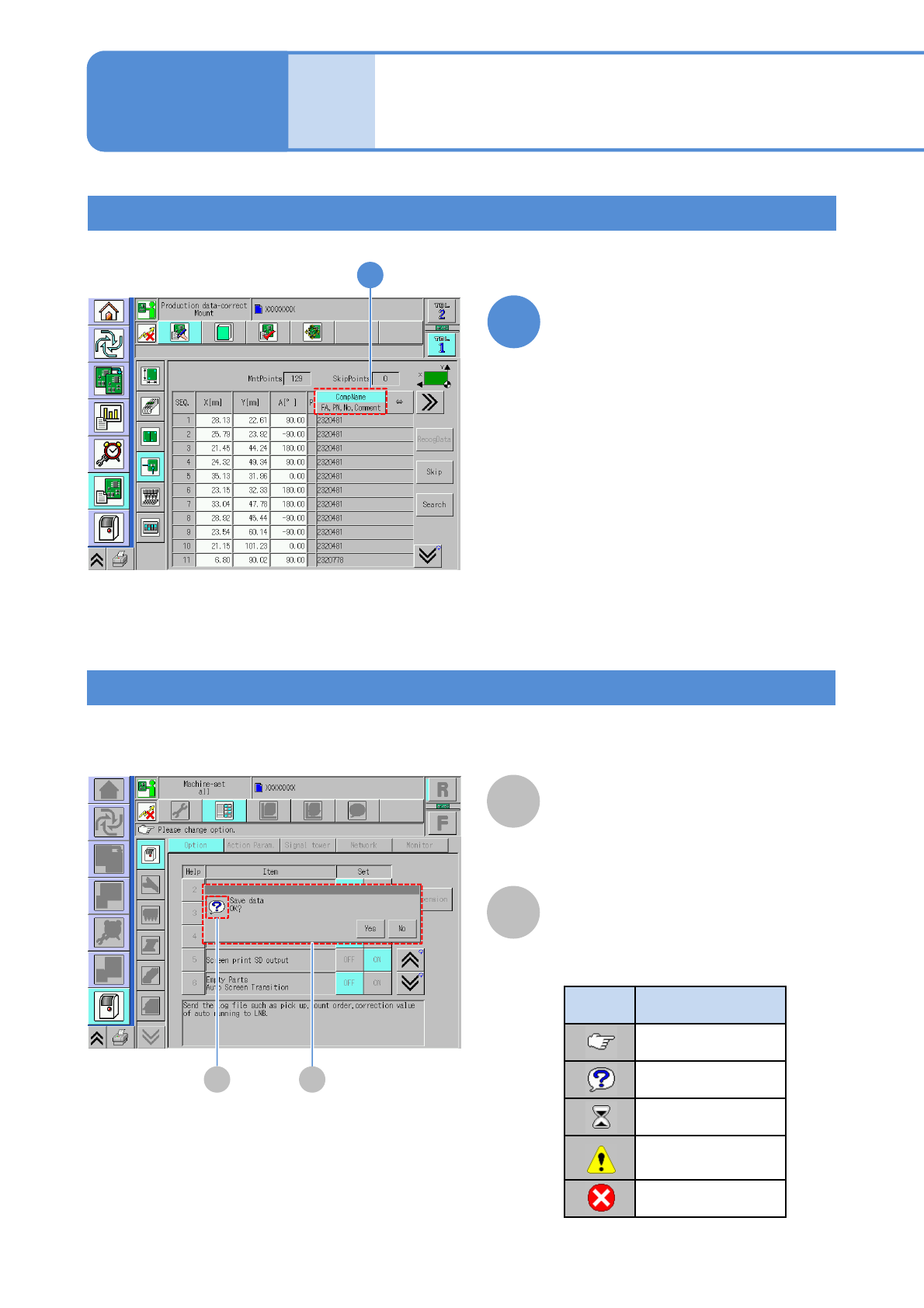
Select the display mode
1
2-2-1-5
Compo-
nent
names
Touchscreen 3
Message (Automatic)
A
A
Message
B
Message icon
Messages are displayed depending on the situation.
●Message icon types
Icon Explanation
Instruction
Inquiry
Time-waiting
Danger, Warning
Caution
Prohibition
B
Operating procedure
2-2-1
NPM-TT2 EJM1EE-MB-02O-04
Table/stage change display 1
2-2-1-6
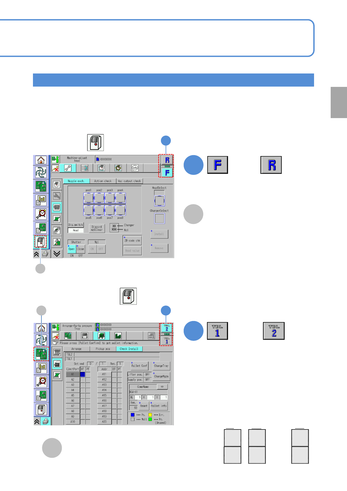
The XY unit is placed in front/rear of NPM-TT2, and the button at the upper-right corner of the screen is
used to switch operations. The display of the table change button varies according to the following conditions.
●What button you have selected in the 1
st
layer
●Where the machine is located in a line when it is coupled together with other equipment
■ Stage change display
(if the 1st layer is )
1
1
or
■Table change display
(If the 1st layer is other than )
1
(Changes the table displayed)
1
A
B
●The display remains the same,
even if the machine is coupled
together with other equipment.
or
●The table change button displays are
numbered sequentially, beginning
from the first machine in line.
First in line
2nd
Nth
TBL
2
TBL
1
TBL
4
TBL
3
TBL
2N
TBL
2N-1
…
…
●Some words in the explanation text are
expressed as follows;
Front side → “F” or “TBL1”
Rear side → “R” or “TBL2”
A
[Machine menu]
B
[Preparation menu]
1st
Preparation
NPM-TT2 EJM1EE-MB-02O-04
Table/stage change display 2
2-2-1-7
Compo-
nent
names
Touchscreen 4
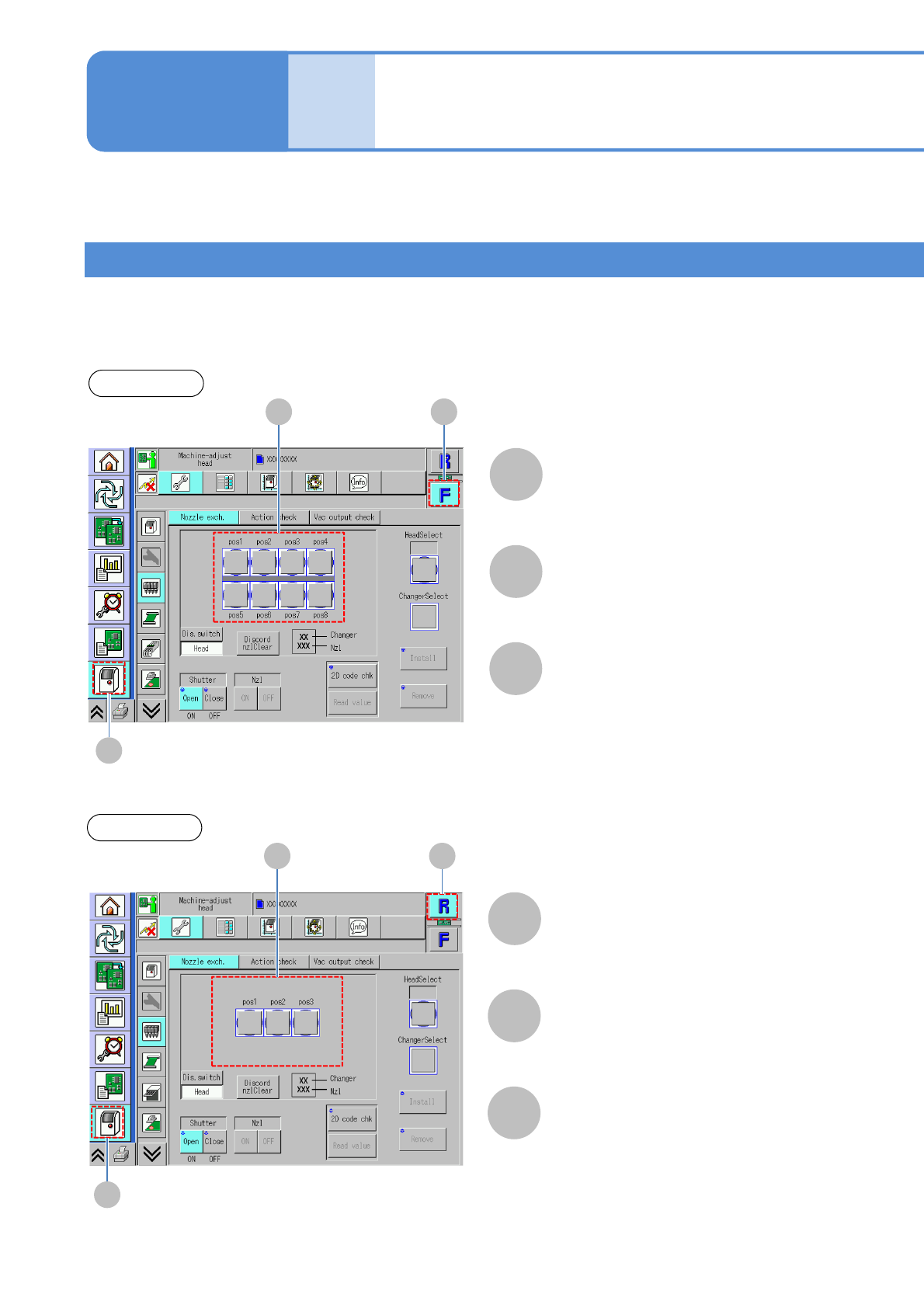
By selecting either the front or rear table, the placement head (including 8- or 3-nozzle head) set to the table
is displayed.
■Sample stage change display
(If the 8-nozzle head is set to the front, and the 3-nozzle head to the rear)
Front table
Drawing of nozzle status
(8-nozzle head)
Front side
C B
A
[Machine menu]
A
B
C
Rear table
Rear side
C B
A
[Machine menu]
A
B
C
Drawing of nozzle status
(3-nozzle head)
Operating procedure
2-2-1