N7201A652E.pdf - 第508页
NPM- TT2 EJM1E E-MB-06O-04 Specifi- cation Suppor t pin automa tic c hange 2 Operating procedure 6-1-9 6-1-9 -3 ■ Arrangement position condition of the s upport pins (for aut omatic change) More tha n the followi ng spac…
NPM-TT2 EJM1EE-MB-06O-04
6-1-9-2
■Handling precautions
1. Do not apply strong impact on the support pin (for automatic change) such as dropping. It may deform
the pin. Also do not use a deformed support pin (for automatic change).
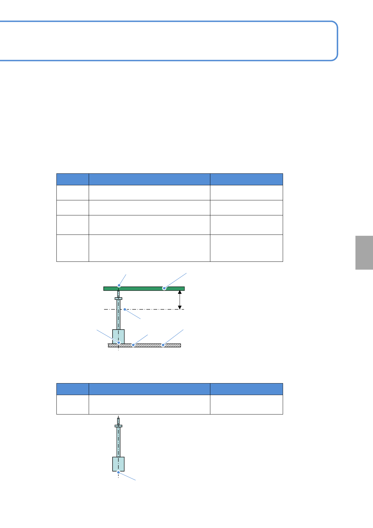
2. The support pin (for automatic change) uses a magnet.
It may have an affect on an electrical component being placed (e.g. inductor). Looking at electrical
component specification and magnetic flux density under the condition described table below, be careful
while handling the support pin.
Symbol Location Magnetic flux density
A
PCB top surface 1.5mT(15G)
B
Bottom of a PCB 28mm 6mT(60G)
C
Support block top surface around the
support pin (for automatic change)
50mT(500G)
D
Between bottom surface of the support pin
(for automatic change) and support block
top surface
500mT(5000G)
●Magnetic flux density (reference value)
Installation condition
28mm
PCB
A
B
D
C
PCB support block
(for automatic change)
Symbol Location Magnetic flux density
E
Support pin (for automatic change) bottom
surface
320mT(3200G)
Single pin condition
E
At
a glance
NPM-TT2 EJM1EE-MB-06O-04
Specifi-
cation
Support pin automatic
change 2
Operating procedure
6-1-9
6-1-9-3
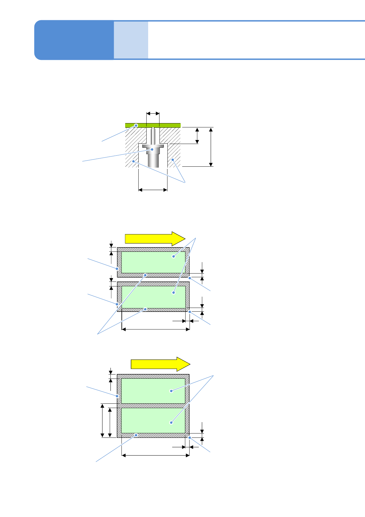
■Arrangement position condition of the support pins (for automatic change)
More than the following space is required between the support pin (for automatic change) and a
component. (Unit: mm)
■Arrangement area of support pins (for automatic change) (Size from PCB front Unit: mm)
PCB
Support pin
(for automatic change)
φ15
28
φ8 (There should be no slit)
Area where a component
enables to exist
6
504
21
6
Lane 2
Lane 1
PCB
outline
Not arrangeable area
PCB
outline
PCB flow direction
Arrangeable area
Reference
Reference
21
2121
504
21
6
PCB flow direction
PCB
outline
Not arrangeable area
Arrangeable area
Reference
21
296
315
●Do not arrange the support pin on the slit.
●PCB dimensions: PC size (Dual lane mode)
●PCB dimensions: PC size (Single lane mode)
NPM-TT2 EJM1EE-MB-06O-04
6-1-9-4
At
a glance
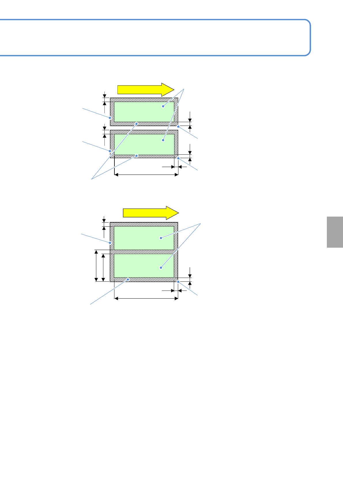
●PCB dimensions: M size (Dual lane mode)
●PCB dimensions: M size (Single lane mode)
504
21
6
Lane 2
Lane 1
PCB
outline
Not arrangeable area
PCB
outline
PCB flow direction
Arrangeable area
Reference
Reference
21
2121
504
21
6
PCB flow direction
PCB
outline
Not arrangeable area
Arrangeable area
Reference
21
238.5
257.5