N7201A652E.pdf - 第496页
NPM- TT2 EJM1E E-MB-06O-04 No zzle specifica tions 1 6-1-6 -1 This ma chine is equipped with the sta ndard nozzles in ea ch head, supporting man y differ ent components. Common to NPM series. Operating procedure 6-1-6 Sp…
NPM-TT2 EJM1EE-MB-06O-04
6-1-5-5
At
a glance
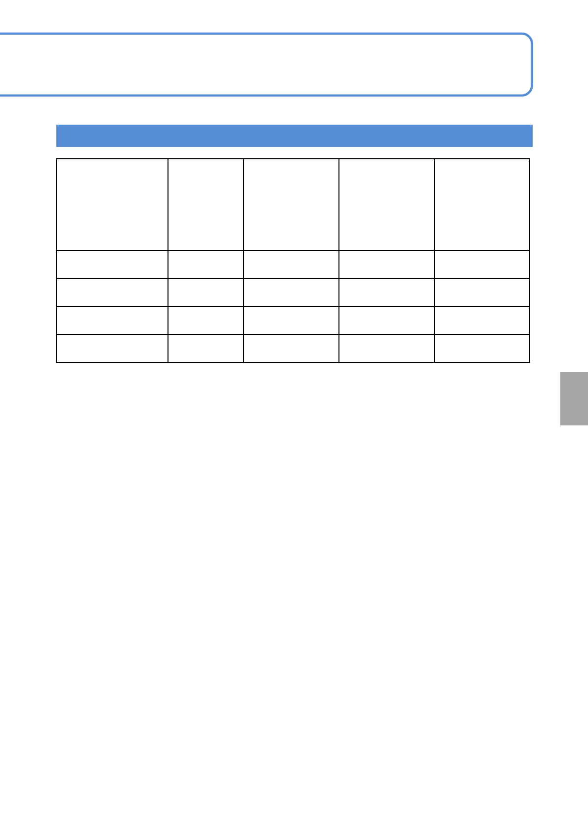
Intelligent stick feeder
*1) The maximum number of feeders installed when the tray feeder (option) is coupled.
*2) The maximum number of feeders installed when feeder carts (option) are coupled to all stages.
*3) Only 13-slot fixed supply unit can be installed. It can be installed to slot No. 19 to 30.
Feeder type
Installation
pitch
(mm)
Maximum number
of feeders
installed when
one single tray
feeder (option) is
coupled
*1)
Maximum number
of feeders
installed when
two single tray
feeder (option)
are coupled
*1)
Maximum number
of feeders
installed when
the feeder carts
(option) are
coupled to all
stages
*2)
Single stick feeder 42 20 12 28
3-rows stick feeder 84 10 6 14
Stackable stick feeder
(S size)*3)
42 12 12 12
Stackable stick feeder
(L size)*3)
84 6 6 6
NPM-TT2 EJM1EE-MB-06O-04
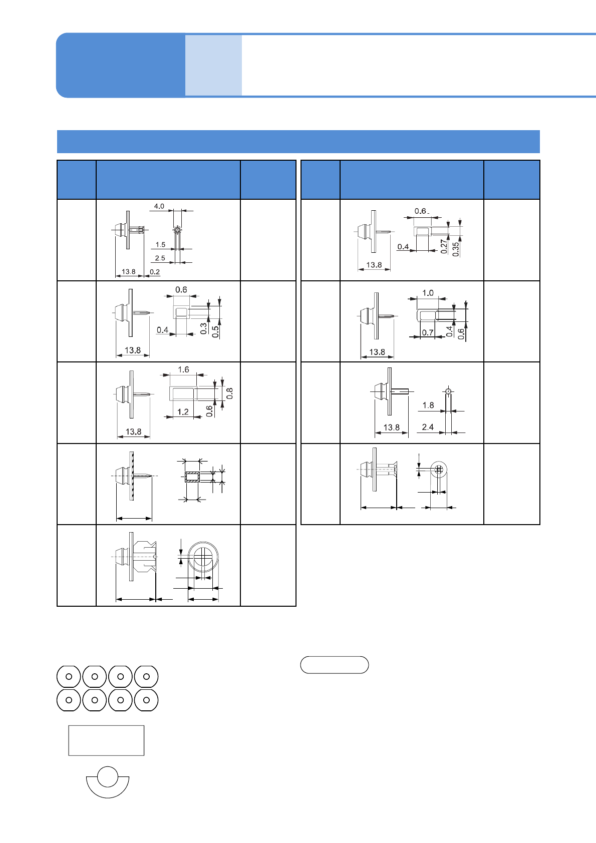
Nozzle specifications 1
6-1-6-1
This machine is equipped with the standard nozzles in each head, supporting many different components.
Common to NPM series.
Operating procedure
6-1-6
Specifi-
cation
8-nozzle head
Nozzle
No.
Shape (mm)
Target
components
(Ex.)
225C
225CN
0603R, C
230C
230CN
1005R, C
1608R, C
240C
240CN
3216R, C
4532R, C
TAN-X,B,C,D
Al electrolytic-
A,B,C
185
185N
SOP
QFP
PLCC
BGA
to 18
× 18 mm
Nozzle
No.
Shape (mm)
Target
components
(Ex.)
140
140N
TAN-D
AI electrolytic-
D
SOP
SOJ
PLCC
CSP
226C
226CN
0603R, C
1005R, C
235C
235CN
1608R, C
2012R, C
3216R, C
SS-Mini Tr, Di
S-Mini Tr, Di
203Z
203ZN
0402R, C
199
199N
SOP
QFP
PLCC
BGA
to 32
× 32 mm
●Even though above nine types are standard for
nozzles for 8-nozzle head, they are available as
nozzles for 8-nozzle head in the CM series.
13.8
6
1.5
0.3
13.8
10
1
1
0.1
6
1234
5678
PCB recognition
camera
NOTICE
1.5
13.8
0.3
0.45
0.32
0.17
●For the nozzle No. including ‘C’, the nozzle tip is made of ceramic.
●For the nozzle No. including ‘N’, the 2D code is provided on the nozzle flange supporting the 2D code
recognition in the NPM series.
.
NPM-TT2 EJM1EE-MB-06O-04
6-1-6-2
1 2 3 4
5 6 7 8
1 2 3 4
5 6 7 8
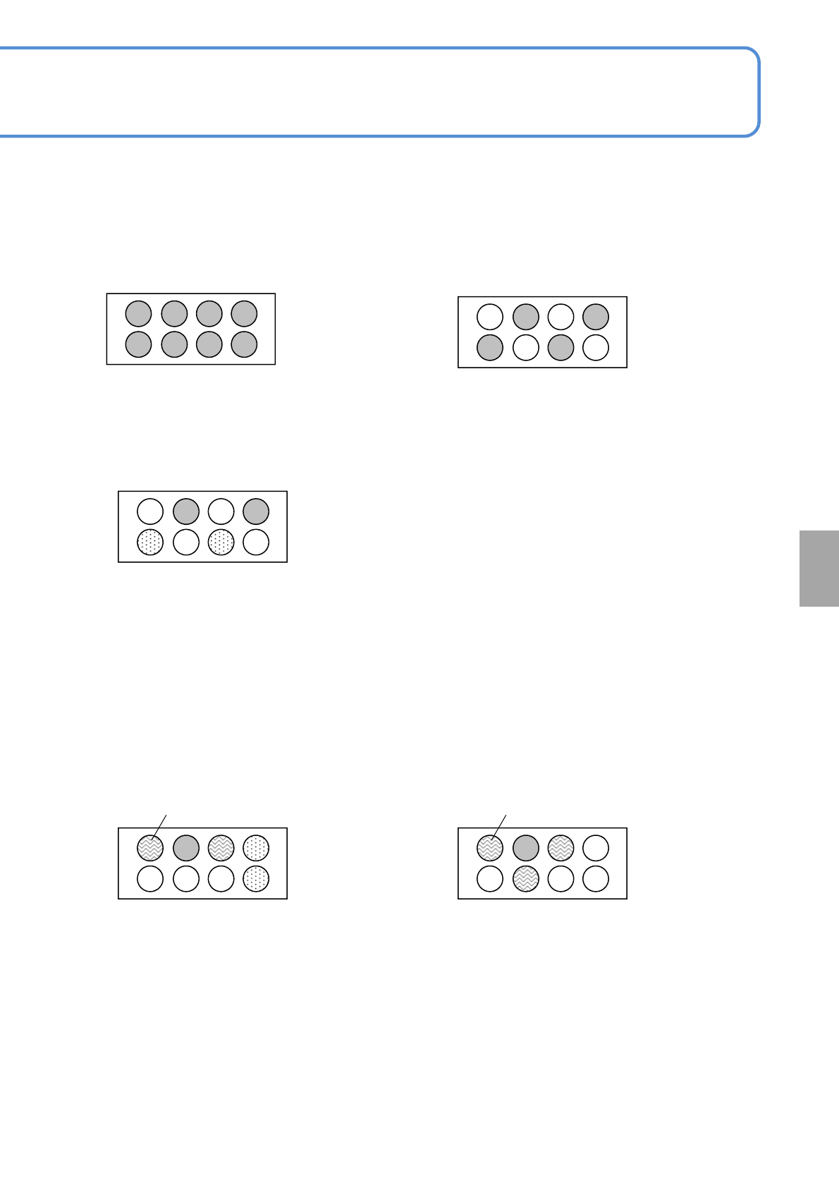
■Pickup component dimensions and nozzle arrangement
( ●: Pickup enabled, ○: Pickup disabled)
*When a component exceeds the size of 24 mm 24 mm, install a recognition nozzle of 4mm or less
in nozzle diameter around its nozzle arrangement position.
(Only for transparent recognition)
●Pickup enabled component:
12 12 mm or less
(A A ≦ 12 12)
●Pickup enabled component:
18 18 mm to 24 24 mm
(18 18 < A A ≦ 24 24)
●Pickup enabled component:
12 12 mm to 18 18 mm
(12 12 < A A ≦ 18 18)
1 2 3 4
5 6 7 8
Components of 12 12 mm or less can be
picked up on ⑤ and ⑦.
Recognition nozzle(φ4mm or less): ①, ③
1 2 3 4
5 6 7 8
●Pickup enabled component:
Component of 24 24 mm to 28 28 mm
(24 24 < A A ≦ 28 28)
Components of 12 12 mm or less can be
picked up on ④ and ⑧.
Recognition nozzle(φ4mm or less): ①, ③, ⑥
1 2 3 4
5 6 7 8
●Pickup enabled component:
Component of 28 28 mm to 32 32 mm
(28 28 < A A ≦ 32 32)
At
a glance