Dek-265GSX-User-Manual.pdf.pdf - 第109页
Parameter Definition Board Thickness This parameter is used by the machine to set correct vision and print heights. Minimum 0.20mm Maximum 6.00mm Increments 0.1mm Underside Clearance This parameter determines the clearan…
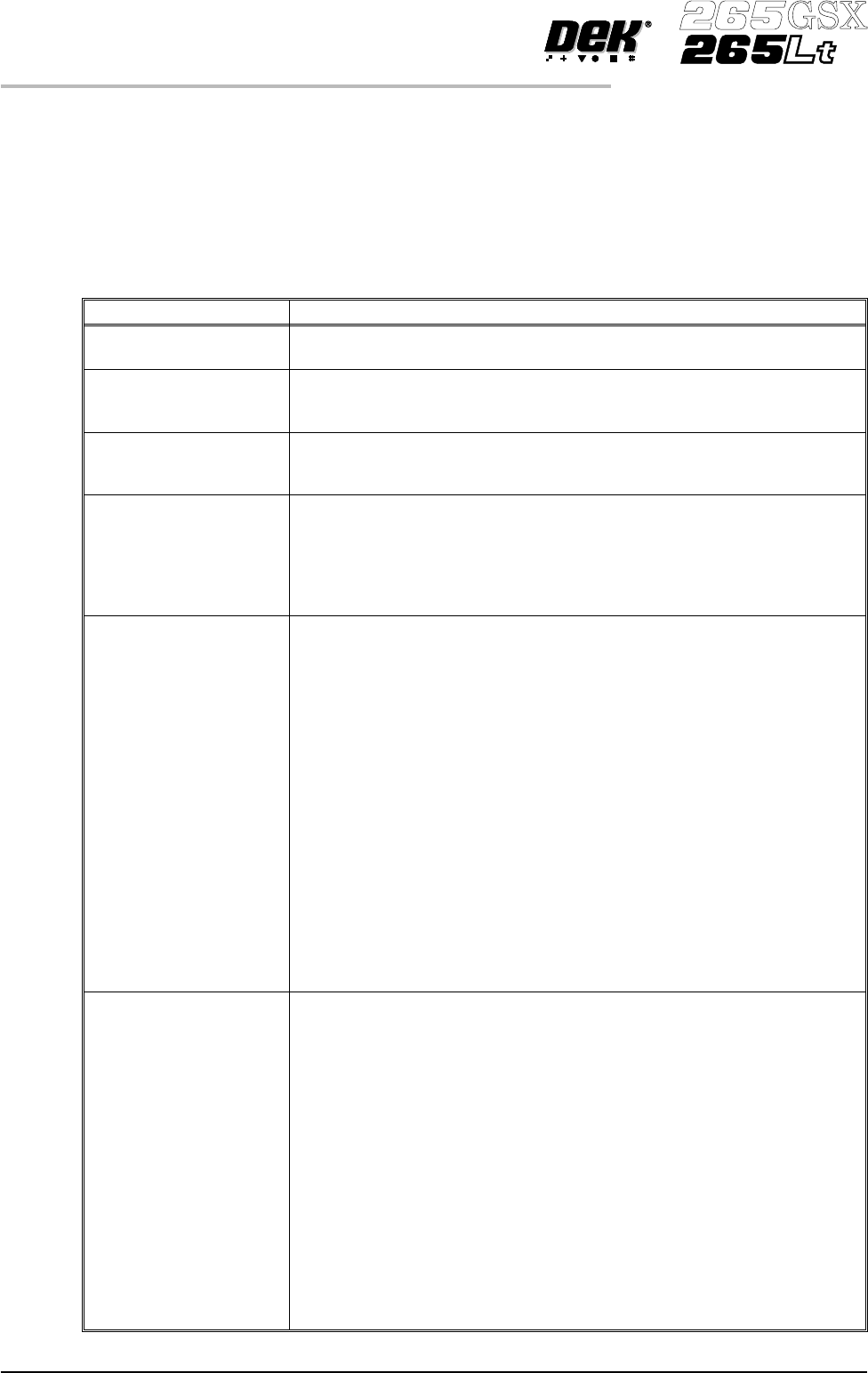
MENU PARAMETERS
Each product has a set of parameters which are unique to that particular product
and which need to be setup to obtain acceptable printing results. These
parametersarelistedbelowwithadefinitionofeachasanaidtomachine setup.
NOTE
Machines running software version 2.06 and above have the ability to read
product files generated by a DEK 288 printing machine.
Parameter Definition
Product Name The file name for the particular product. The name can consist of up to eight
alphanumeric characters with no punctuation.
Product ID The product ID is a parameter that allows a descripton of the product. This
string may be up to 32 characters long, but only the first 20 characters are
displayed.
Product Barcode
(265GSX only)
The barcode number for the particular product. The barcode can be up to
twenty characters long. This parameter is only used if the machine is fitted
with a product barcode reader.
Screen Barcode (265GSX
only)
The barcode number that identifies the particular screen to be used with this
particular product. The barcode can be up to twenty characters long. If the
screen has a barcode printed on it in the correct place and the machine is
initialized to read the code, the screen is checked to ensure it is correct after it
has been fitted. If it is incorrect a message is displayed on the monitor. This
parameter is only used if the machine is fitted with a product barcode reader.
Board Length This parameter is used to set the default values for the board stop position in
the X direction, the paste dispensing area, and the AutoFlex reset columns.
The maximum value depends on the type of screen selected.
Min. Allowable 50mm (see Note 1.)
Max. Allowable
265 508mm (see Notes 1. and 2.)
255 460mm
249 430mm
Fuji 460mm
Sanyo 420mm
Heraeus 344mm
In increments of 0.1mm
NOTE
1. With remote board stop fitted
Min. Allowable 130mm
Max. Allowable 508mm (see Note 2.)
2. With the large board option the Max. Allowable is 620mm.
Although the maximum parameter is 620mm boards of
664mm can be loaded.
Board Width This parameter sets the rail width for this particular product. It is also used to
set a default value for the print stroke, the clean screen, the board stop
position in the Y direction, and the autoflex rows. The maximum value
depends on the screen type selected.
Min. Allowable 40mm
Max. Allowable
265 508mm
255 432mm
249 330mm
Fuji 460mm
Sanyo 284mm
Heraeus 344mm
In increments of 0.1mm
NOTE
With remote board stop fitted
Min. Allowable 119mm
Max. Allowable 508.5mm
1.92 User Manual Software Version 6
MACHINE PROGRAMMING
MENU PARAMETERS
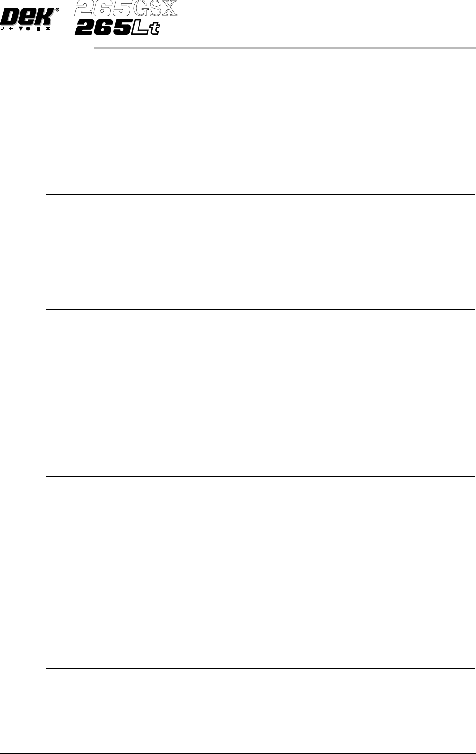
Parameter Definition
Board Thickness This parameter is used by the machine to set correct vision and print heights.
Minimum 0.20mm
Maximum 6.00mm
Increments 0.1mm
Underside Clearance This parameter determines the clearance provided between the underside of
the board and the top of the machine tooling to allow for components on the
underside of the board.
Minimum 3mm
Maximum 42mm
Increment 0.1mm
Default 19mm
Tooling Type This determines which type of board support is to be used with this particular
product. Options are:
Autoflex, Vacuum, Magnetic Pillars, Vac for Flex
See Tooling
Flatten Vacuum Delay This parameter determines the duration of vacuum applied whilst the board is
pressed against the underside of the screen with Vac for Flex enabled.
Minimum 0 sec
Maximum 5 secs
Default 2 secs
Increment 0.1 sec
Separation Vacuum
Delay
This parameter determines the duration of the vacuum applied after printing
and before the rising table is lowered to separation height with Vac for Flex
enabled.
Minimum 0 sec
Maximum 5 secs
Default 2 secs
Increment 0.1 sec
Print Front Limit This determines the distance from the front edge of the board that printing
must start.
Minimum -6.5mm
Maximum Board width set into the board file
Increment 0.1mm
Default 0mm
NOTE
With Paste Trails enabled or ProFlow fitted the minimum value is 0mm
Print Rear Limit This determines the distance from the rear edge of the board that printing
must start.
Minimum -6.5mm
Maximum Board width set into the board file
Increment 0.1mm
Default 0mm
NOTE
With Paste Trails enabled or ProFlow fitted the minimum value is 0mm
Board Stop X This parameter determines the distance from the centre line of the machine to
the board stop position.
Minimum 50mm
Maximum 310mm
Increment 0.1mm
Default Half of the board length set in the board
file, (Board located centrally)
NOTE
Not used while remote board stop is fitted.
Software Version 6 User Manual 1.93
MACHINE PROGRAMMING
MENU PARAMETERS
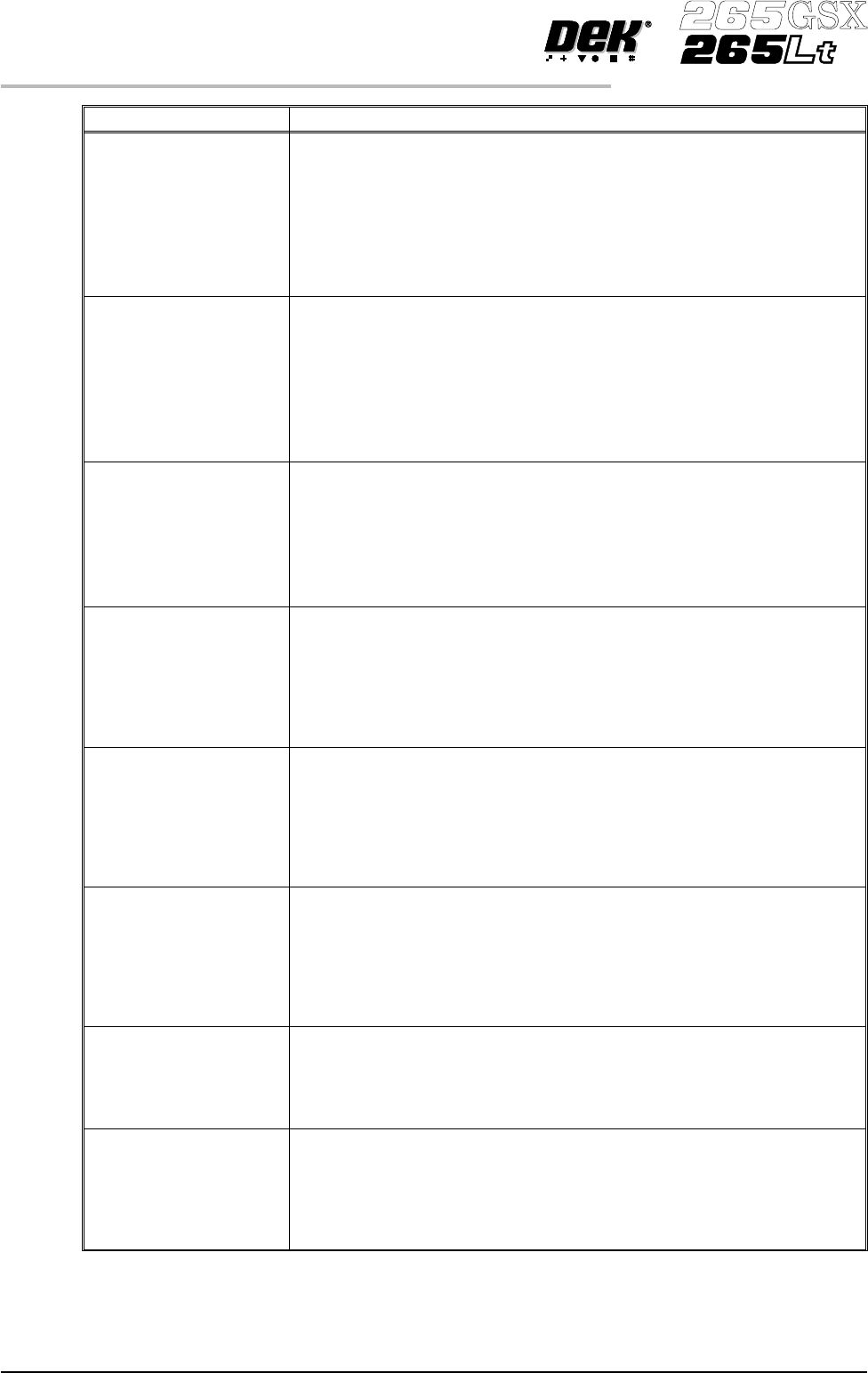
Parameter Definition
Board Stop Y This parameter determines the distance from the fixed rail to the board stop
position.
Minimum 25mm
Maximum Board width minus 20mm
Increment 0.1mm
Default Two thirds of the board width
NOTE
Not used while remote board stop is fitted.
Remote Board
Stop X
This parameter determines the displacement of the remote board stop from
the camera reference position.
Minimum Minimum Board Length ö 2
Maximum Board Length
Increment 0.1
Default Board Length ö 2
NOTE
Only used while remote board stop is fitted.
Right Feed Delay This parameter sets a time delay on the board stop to allow for irregular
shaped boards when fed from the right.
Minimum 0sec
Maximum 3secs
Increments 0.1sec steps
NOTE
Not used while remote board stop is fitted.
Alignment Weighting This is only used in 2 fiducial mode. This parameter sets a value determining
how much of the fiducial spacing error is assigned to fiducial 2.
Minimum 0%
Maximum 100%
Increment 1%
Default 50%
See vision system
X Align Weighting This is only used in 3 fiducial mode. This parameter sets a value determining
where the X axis alignment should be optimized.
Minimum 0%
Maximum 100%
Increment 1%
Default 50%
See vision system
Y Align Weighting This is only used in 3 fiducial mode. This parameter sets a value determining
where the Y axis alignment should be optimized.
Minimum 0%
Maximum 100%
Increment 1%
Default 50%
See vision system
Alignment Mode This parameter determines the mode used for board to screen alignment. The
Non Vision option is only available from the configuration file. Options
available are:
2 fiducial; 3 fiducial.
Default 2 fiducial
Fiducial 1 X coordinate Distance of first fiducial from the right or left hand edge of the board
(configuration dependent).
Minimum 1mm
Maximum Board Length
Increment 0.1mm
Default 1mm
1.94 User Manual Software Version 6
MACHINE PROGRAMMING
MENU PARAMETERS