Dek-265GSX-User-Manual.pdf.pdf - 第212页
PROFLOW The ProFlow diagnostic module contains the following: The menu bar changes to the following: Run Diagnost activates the diagnostic function, as selected by the highlight bar. Next/Previous keys move the highlight…

Drive Carriage to
Front Position
Selecting this option moves the print carriage to the front start position of the
print stroke. “Driving Print Carriage to Front Limit” is displayed in the prompt
box.
Drive Carriage to
Paste Position
Selecting this option moves the print carriage to a position that clears the paste
dispense unit ifoperated. “Driving Print Carriage to Paste Position” is displayed
in the promt box.
Drive Carriage to
Rear Position
Selecting this option moves the print carriage to the end of the print stroke.
“Driving Print Carriage to Rear Limit” is displayed in the prompt box.
Drive Carriage
Using Jog Buttons
Selecting this option allows the user to position the print carriage anywhere
between the front and rear position using either of the two button safety switches
located on the front of the machine. “Use the Left Jog Button to move Print
Carriage towards front and the Right Jog Button to move it towards the rear” is
displayed in the prompt box.
Cycle Print
Carriage
Selecting this option starts a continuous cycle of driving the print carriage
between its front and rear limits pausing at the each end for 2 seconds. “Print
Carriage Cycling” is displayed in the prompt box. The speed is measured and
displayed. The cycle is terminated if the Stop key is used or that the set cycle
count is reached.
Cycle Count This option displays the count when the module is being cycled.
Software Version 6 User Manual 5.17
DIAGNOSTICS
PRINT CARRIAGE
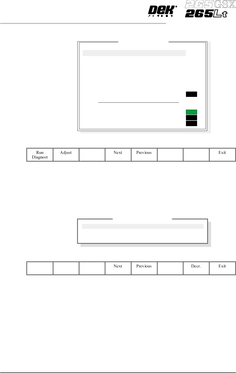
PROFLOW The ProFlow diagnostic module contains the following:
The menu bar changes to the following:
RunDiagnost activates the diagnostic function, as selected by thehighlightbar.
Next/Previous keys move the highlight bar up and down the list of selectable
diagnostic functions.
Exit returns operation to the module diagnostics page.
Adjust opens the following window:
The menu bar changes to the following:
Incr.
Next/Previous keys move the highlight bar up and down the list of diagnostic
parameters.
Incr./Decr. keys change the value of the selected diagnostic parameter.
Exit returns operation to the ProFlow diagnostics page.
Home ProFlow Selecting this option drives the ProFlow unit up to the home position. If the
downstop is in the way a warning is displayed.
5.18 User Manual Software Version 6
DIAGNOSTICS
PROFLOW
ProF
l
ow D
i
agnost
i
cs
3.3kg
ON
OFF
OFF
OFF
Home ProFlow
Drive System to Contact Height
Drive System to Print Height
Home Downstop
Drive Downstop to Position
Drive System Using jog Buttons
Drive Downstop Using jog Buttons
Toggle Paste Pressure
Pressure Reading
ProFlow Fitted
Paste Cassette Low
ProFlow Pressure Regulator Fitted
ProFlow Adjust Parameters
PFLOW CONTACT POS.
PFLOW DSTOP POS.
IDLE PRESSURE
0.0
0.0
0.2
mm
mm
bar

Drive System to
Contact Height
Selecting this option drives the ProFlow unit onto the screen, (a slight pressure
seal, is made between the ProFlow transfer head and the screen). There is no
pressure applied to the paste cassette.
Drive System to
Printing Height
Selecting this option drives the ProFlow transfer head down to printing pressure
(as setup in the Edit Data board file). There is no pressure applied to the paste
cassette at this time.
Home Downstop Selecting this option drives the downstop to home position (fully raised).
Drive Downstop
to Position
Selecting this option drives the downstop to the preset downstop position (offset
canalsobeadjustedinthestatusmenupage by selecting Maint. and selecting Set
Prefs menu).
Drive System
Using Jog Buttons
Moves the ProFlow unit up or down by means of the jog buttons.
Drive Downstop
Using Jog Buttons
Moves the downstop up or down by means of the jog buttons.
Toggle Paste
Pressure
Initiates pressure onto the paste system. Before initiating pressure to the paste
system, the transfer head must be in contact with,and have an adequate seal with
the screen. A warning is displayed if toggle paste pressure is selected with the
transfer head off the screen.
Pressure Reading Continuously displays the current pressure in kg exerted from the squeegee
pressure load cell onto the ProFlow unit.
ProFlow Fitted Indication of electrical connection of ProFlow to the machine software.
Paste Cassette Low ProFlow paste low sensor activated (on), indicating paste low or empty or,
deactivated (off).
ProFlow Pressure
Regulator Fitted
Switched to OFF indicates that the ProFlow unit is fitted with a mechanical
pressure regulator control. Switched to ON indicates that the software
addressable regulator control is activated, (ProFlow unit not fitted with
mechanical pressure regulator).
Software Version 6 User Manual 5.19
DIAGNOSTICS
PROFLOW