Dek-265GSX-User-Manual.pdf.pdf - 第291页
5. Ensure the lighting histogram has a good definition of grey scale levels, as shown below. 6. Select Exit . Exit Learn Site 1. Select Learn Site . Learn Site Dependent upon the 2D inspect type selected, the ‘Screen Lea…
2.
Using the Next, Previous, Incr. and Decr. keys, adjust the lighting
parameters to a level whereby the screen and board pads are just whiting out,
without blooming, default level 8 is usually adequate for the majority of
setups.
Next Previous Incr. Decr.
3. For machines with a green camera go to Step 6. For machines with a silver
camera continue with Step 4.
4. Adjust the set light graphic using the window left, window top, window
width and window height parameters to surround the feature providing 50%
black and 50% white.
8.26 User Manual Software Version 6
2Di INSPECTION
2Di SETUP
8
8
8
8
8
8
8
8
8
8
-1.0
-1.5
2.0
2.0
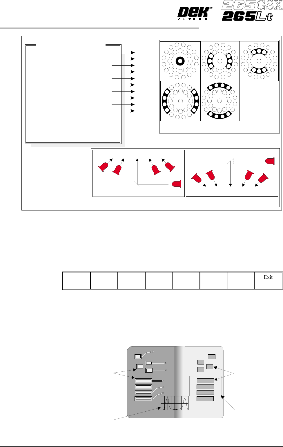
Inspection Lighting Parameters
Screen Vertical
Screen Inner LR
Screen Inner FR
Screen Outer LR
Screen Outer FR
Board Vertical
Board Inner LR
Board Inner FR
Board Outer LR
Board Outer FR
Window Left
Window Top
Window Width
Window Height
A
B
C
D
E
A
B
C
D
E
NOTE
LR = Left and Right
FR=FrontandRear
Camera Lighting
Plan View Figure:
Screen Camera Lighting (Side View)
Prism
Outer
Inner
Inner
Vertical
Outer
LED
Board Camera Lighting (Side View)
Outer
Inner
Vertical
Inner
Outer
Prism
LED
Plan View of Camera Lighting LEDs
(Board or Screen)
A
B
C
D
E
Figure 8-15 Lighting Parameters - Silver Camera
Aperture
Board Pad
Set Light
Graphic
Underside of Screen
Histogram
Top of Board
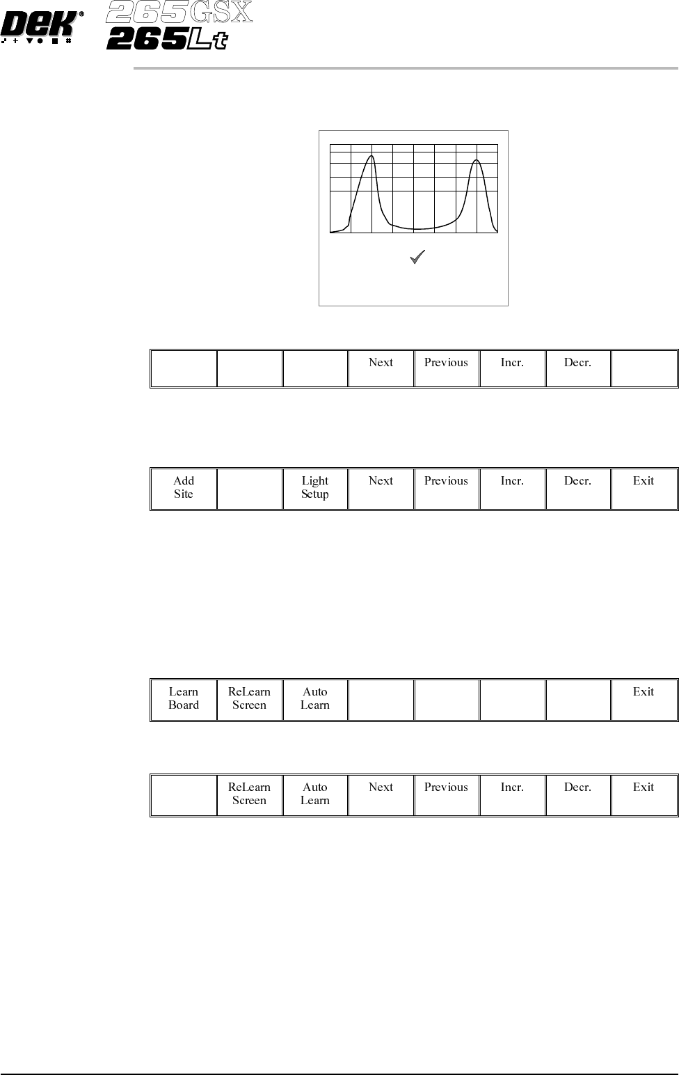
5. Ensure the lighting histogram has a good definition of grey scale levels, as
shown below.
6.
Select Exit.
Exit
Learn Site 1.
Select Learn Site.
Learn
Site
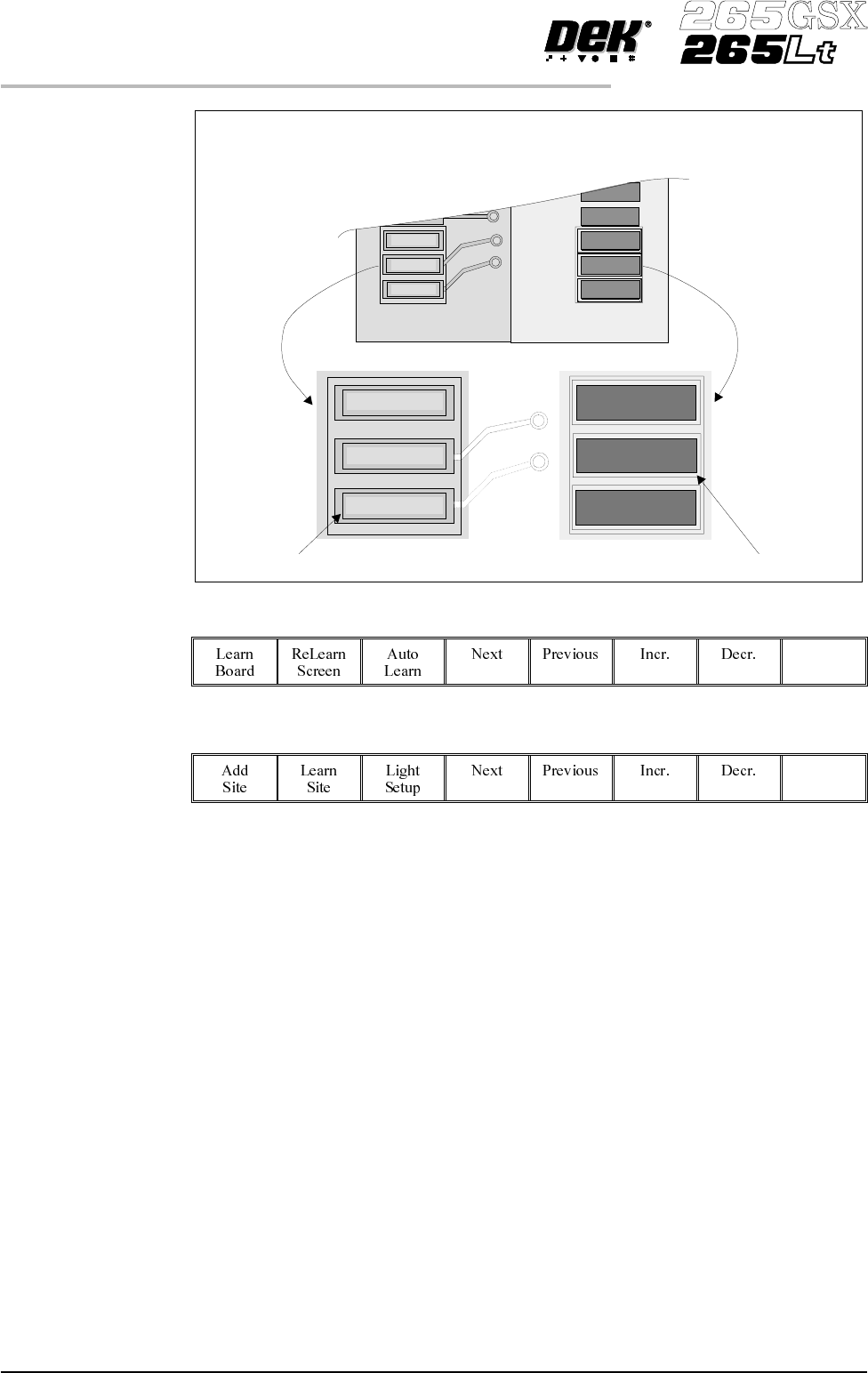
Dependent upon the 2D inspect type selected, the ‘Screen Learnt’ message is
displayed in the message prompt bar above the menu bar. The apertures within
the site are enclosed by individual graphic boxes, as shown over the page. If
‘....Screen Not Learnt’ is displayed, adjust the site parameters and re-learn the
site.
2.
Using the Next, Previous, Incr. and Decr. keys adjust the board graphic X
andboard graphic Y coordinates to achieve graphic alignment on theboard.
Next Previous Incr. Decr.
3.
Select Learn Board.
Learn
Board
4.
The message ‘Board Learnt’ is displayed in the message prompt bar above
the menu bar. If ‘....BoardNot Learnt’is displayed, edit thesite parameters
and re-learn the site.
NOTE
1. If the size of the graphic box for the site is altered, the screen has to be
re-learnt and this step repeated.
2. Exiting without learning, loses the edited information.
3. The number of pads must equal the number of apertures for a successful site.
4. Adjust the board graphic X and board graphic Y accurately, as this is used as
a reference for alignment measurements.
Software Version 6 User Manual 8.27
2Di INSPECTION
2Di SETUP
Lighting parameters correctly set
5.
Select Exit.
Exit
6.
Select Exit.
Exit
8.28 User Manual Software Version 6
2Di INSPECTION
2Di SETUP
The site learnt graphics appear around the screen aperture and on the board pads
confirming that the site is learnt. If necessary, adjust the mirror image board site
graphic over the corresponding pad.
Screen site learnt boxBoard site learnt box