Dek-265GSX-User-Manual.pdf.pdf - 第374页
1. Press Setup (F6). Setup 2. Press Setup ProFlow (F4). Setup ProFlow 3. Press Change ProFlow (F1). Change ProFlow The message ‘ Replace ProFlow Cover Plate then Close Cover and Press Continue ’ is displayed. 4. Open the…
11. If the set preference is set to suspend, the following window is displayed:
The tricoloured beacon shows red.
12.
Select Refill Paste (F1).
Refill
Paste
The message ‘Open the cover and change the ProFlow cassette.’ is
displayed.
13.
Select Open Cover (F2).
Open
Cover
14. Carry out Steps 19-33 of Prior to a Print Run procedure, earlier in this
section.
15.
Select Continue (F1). The print run resumes.
Continue
Paste
Retention System
Replacement
Due to wear over prolonged periods, it is necessary to replace the wiper foils and
end retainers (skis). An obvious indication of blade deterioration is print
medium left deposited on the screen after a print cycle.
Replace the wiper foils and end retainers (skis) as follows:
Software Version 6 User Manual 9.59
CONSUMABLE REPLENISHMENTS
PROFLOW
WARNING
SOLDERPASTEANDSOLVENTS. WHENUSINGORHANDLINGAN
Y
SOLDER PASTE OR SOLVENT FORMULATION THE
MANUFACTURERS' RECOMMENDED SAFETY PRECAUTIONS
MUSTBESTRICTLYADHEREDTO.
WARNING
PROTECTIVE CLOTHING. APPROVED PROTECTIVE CLOTHIN
G
SHOULD BE WORN BY SOLDER PASTEAND SOLVENT HANDLERS
AT ALL TIMES TO ELIMINATE FUME INHALATION, EYE
CONTACT,SKINCONTACTANDINGESTION.
1.
Press Setup (F6).
Setup
2.
Press Setup ProFlow (F4).
Setup
ProFlow
3.
Press Change ProFlow (F1).
Change
ProFlow
The message ‘Replace ProFlow Cover Plate then Close Cover and Press
Continue’ is displayed.
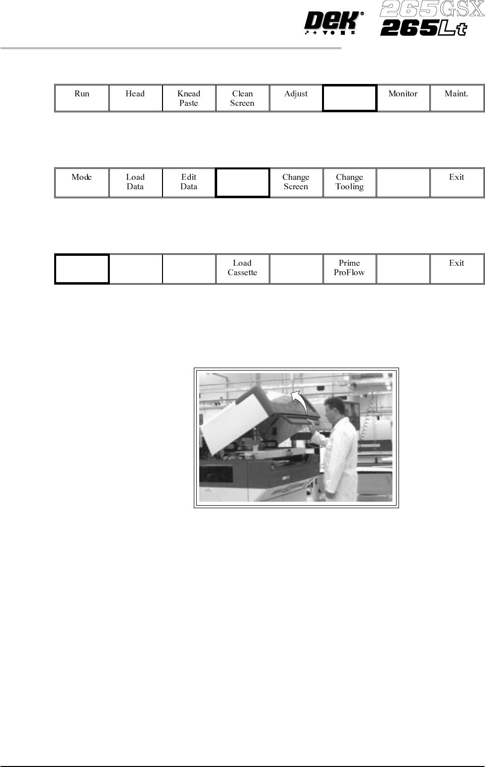
4. Open the front printhead cover.
5. Fit the paste cover to the underside of the ProFlow transfer head unit.
6. Release the latch on the front of the pressure mechanism and raise the
mechanism forwards and upwards to engage the spring locking device.
7. Turn the rotary action ‘J’ latch anticlockwise to release the transfer head unit
from the pressure mechanism. Lift the rotary ‘J’ latch clear of the transfer
head chassis dowel to enable the transfer head to be lowered from the two
interface mounting rods.
9.60 User Manual Software Version 6
CONSUMABLE REPLENISHMENTS
PROFLOW
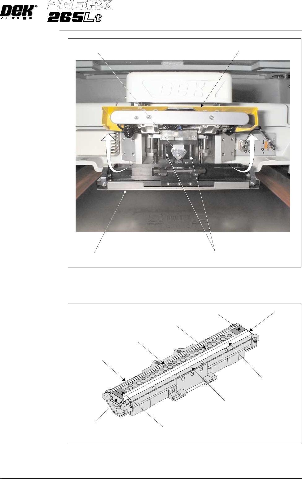
8. Invert the ProFlow transfer head and place onto the maintenance stand
(provided with the equipment).
9. Remove the paste cover from the ProFlow transfer head unit.
10. Carefully remove the wipers by loosening the six screws securing the wiper
retaining strips.
Software Version 6 User Manual 9.61
CONSUMABLE REPLENISHMENTS
PROFLOW
Pressure Mechanism (Raised for Access)
Rotary Action ‘J’ Latch
ProFlow Transfer Head
Interface Mounting Rods (in 2 positions)
Wiper
Secondary Grid (Stainless Steel)
Wiper
Wiper Retaining Strip
Wiper Retaining Strip
End Retainer (Ski)
End Retainer (Ski)
Retainer Bracket
Retainer Bracket
Transfer Head Inverted