Dek-265GSX-User-Manual.pdf.pdf - 第62页
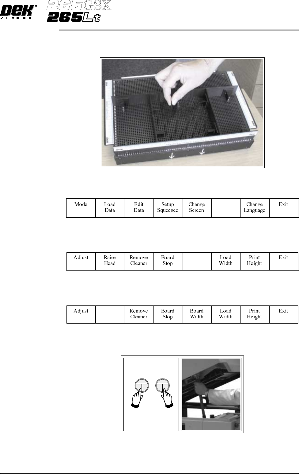
10. The MultiFlex tooling can now be fitted into the appropriate location holes in the tooling plate. Ensure that the tooling is placed into the correct set of holes, taking regard of the type of screen being used and he…
5. Using the grid co-ordinates marked on the template, position pins which
coincide with gaps between the underside board components.
6.
Select Change Tooling (F6).
Change
Tooling
7.
Select Full Width (F5).
Full
Width
8.
Select Raise Head (F2).
Raise
Head
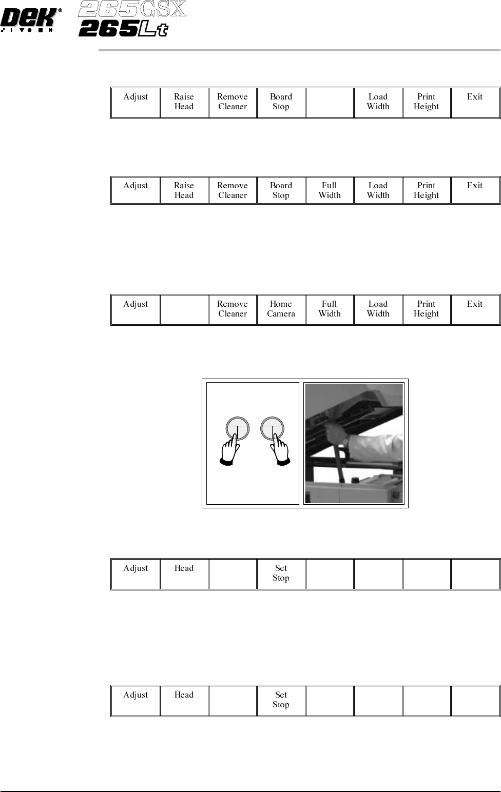
9. Raise the printhead using two button control. Fit the head prop.
Software Version 6 User Manual 1.45
MACHINE PROGRAMMING
STAGE 6D
10. TheMultiFlextoolingcannowbefittedintotheappropriatelocationholesin
the tooling plate. Ensure that the tooling is placed into the correct set of
holes, taking regard of the type of screen being used and hence the position
of the fixed rail.
11.
Select Head (F2).
Head
12. Remove the head prop. Lower the printhead using two button control.
13.
Press the System button.
1.46 User Manual Software Version 6
MACHINE PROGRAMMING
STAGE 6D
14.
Select Board Width (F5).
Board
Width
15.
Select Board Stop (F4).
The camera moves to the board stop position. The board stop on the camera
extends.
16.
Select Raise Head (F2).
Raise
Head
17. Raise the printhead using two button control. Fit the head prop.
18.
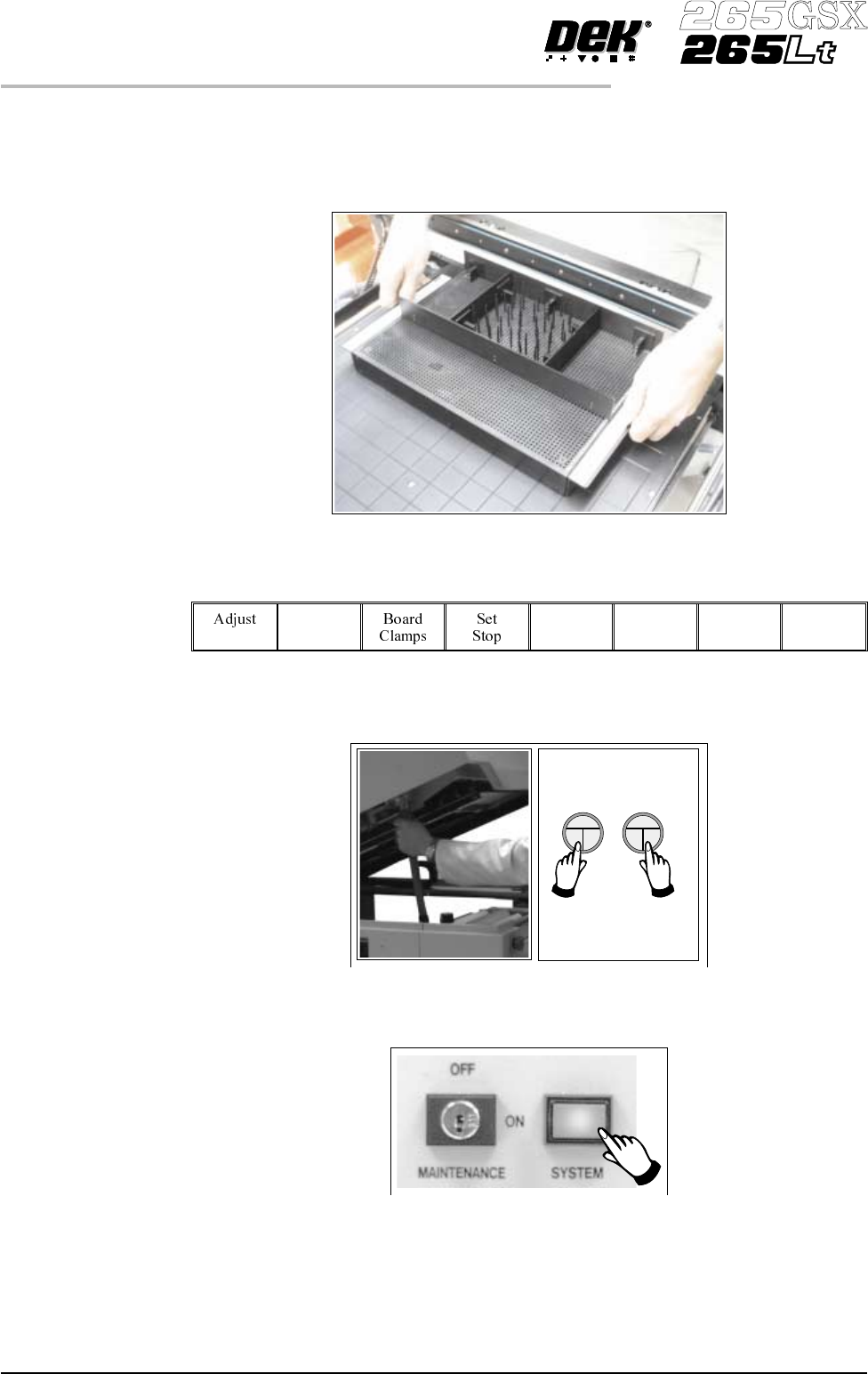
Select Board Clamps (F3), to open the clamps.
Board
Clamps
19. Slide a board along the rails to abut the board stop.
20.
Select Board Clamps (F3), to close the clamps.
Board
Clamps
Software Version 6 User Manual 1.47
MACHINE PROGRAMMING
STAGE 6D