Dek-265GSX-User-Manual.pdf.pdf - 第37页
15. Press the System button on the control console. For edge justified screen images the screen is automatically clamped in place, providing the screen has been pushed fully in against the stops. 16. For centre justified…
9. If an Adjustable Screen Spacer is to be used proceed to Step 10.
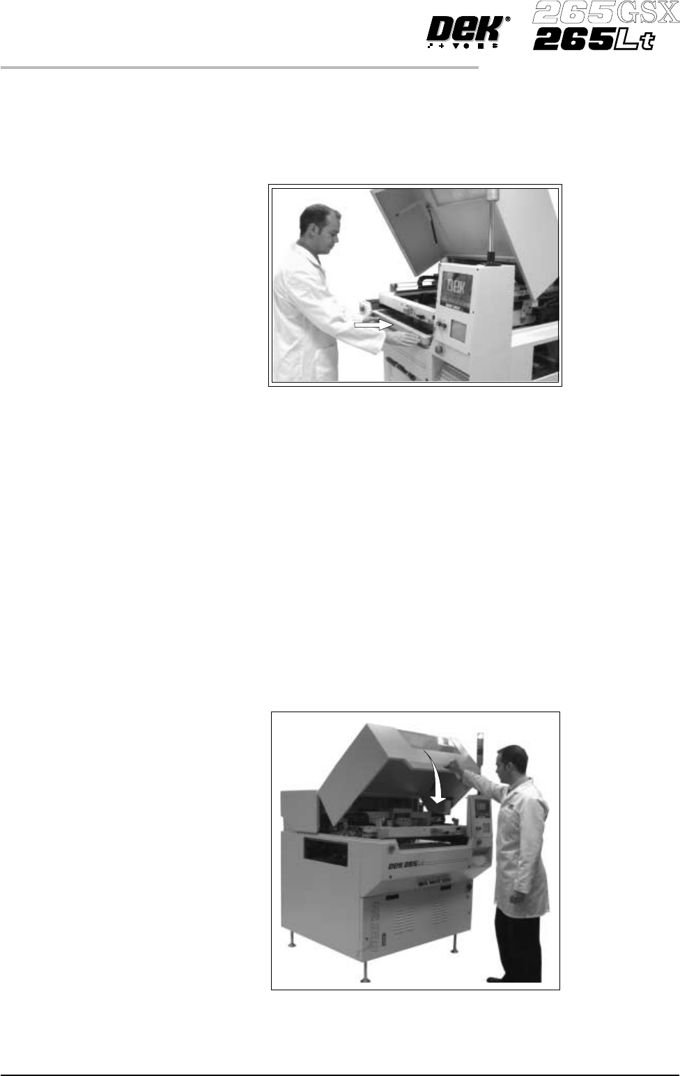
Fit the new screen into the printhead ensuring the correct orientation of the
screen. For edge justified screen imagespushthescreenfullytotherear. For
centre justified screen images correctly position the screen using the
graduated scale. Proceed to Step 14.
NOTE
For the adjustable Screen Spacer setup, see Technical Reference Manual,
Screens and Screen Images Chapter.
10. Slide the adjustable screen spacer partly into the chase, with the jack screws
facing towards the rear of the machine.
11. Slide the screen into the chaseuntilitengageswiththescreencatch plates of
the adjustable screen spacer.
12. Slide the screen and spacer towards the rear of the chase until the spacer
makes contact with the chase stops.
13. Press gently against the front of the screen, to ensure that there is no gap
between the screen and spacer or the spacer and chase stops.
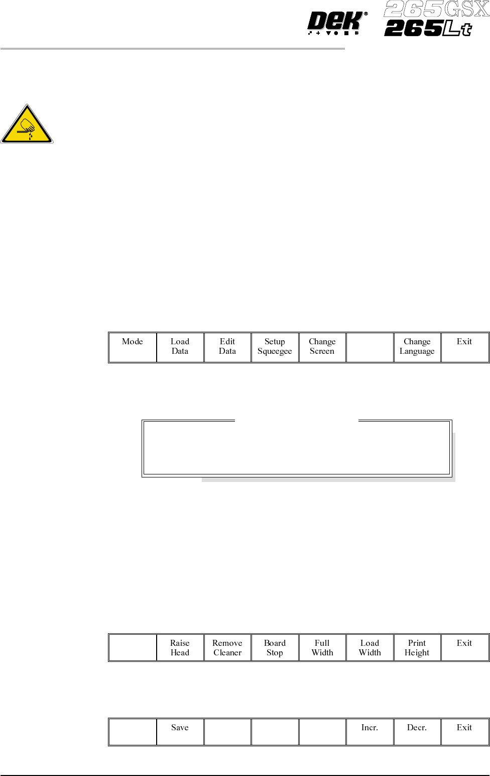
14. Lower the printhead cover.
1.20 User Manual Software Version 6
MACHINE PROGRAMMING
STAGE 5B

15.
Press the System button on the control console.
For edge justified screen images the screen is automatically clamped in
place, providing the screen has been pushed fully in against the stops.
16.
For centre justified screen images only, press Confirm, the screen is
automatically clamped in place.
17. Continue to Stage 6 - Tooling Setup.
CAUTION
SCREEN NOT LOADED. Pressing Confirm without a screen loaded,
could result in serious machine damage.
Software Version 6 User Manual 1.21
MACHINE PROGRAMMING
STAGE 5B
STAGE 6A
Tooling Setup - Magnetic Pillars
CAUTION
BOARD CLAMPS. Care must be taken to ensure that the board clamps
are not damaged when removing or replacing tooling.
Board Stop Setting up the board stop position is automatically done using the board
dimensions previously setin the boardparameter file. If adjustment is necessary
proceed as follows:
1.
Select Change Tooling (F6).
Change
Tooling
The Change Tooling Parameters window is displayed:
NOTE
If the remote board stop is fitted the Board Stop X and Board Stop Y parameters
are replaced by Remote Board Stop X.
These parameters are automatically calculated from the board size parameters
that were entered in the product file. If they need adjustment to re-position the
board stop for any reason, ie any routing on the board edge or a badly positioned
image on the screen, this can be done now.
2.
Select Adjust (F1).
Adjust
3.
Use the Next and Previous keys (F4 - F5) to highlight each parameter.
Next Previous
1.22 User Manual Software Version 6
MACHINE PROGRAMMING
STAGE 6A
WARNING
BOARD CLAMPS. EXTREME CARE MUST BE EXERCISED WHEN
WORKING IN THE TOOLING AREA OF THE MACHINE TO AVOID
INJURY. THE FOILS ON THE FRONTAND REAR BOARD CLAMPS
AREVERYSHARP.
Change Tooling Parameters
BOARD WIDTH
BOARD STOP X
BOARD STOPY
216.0
125.0
142.6
mm
mm
mm