Dek-265GSX-User-Manual.pdf.pdf - 第274页
Histogram The Cognex card analyses the grey scale levels, of the pixels that make up the site image. From this information a histogram is produced, which can be used as a visual aid to setting up 2Di inspection. Lighting…
Inspection Cycles During setup, sites are given a priority of either Every Cycle (EC) or General
(G). The amount of sites inspected during each cycle is set using the min
sites/cycle parameter, this must be set to at least the amount of every cycle sites.
As the name suggests, EC sites are inspected every cycle. General sites are
inspected depending on the value of the min sites/cycle parameter and the
number of EC sites as follows:
Number of general sites inspected per cycle = Min sites/cycle parameter - EC
sites.
The general sites are inspected in rotation as shown below.
Software Version 6 User Manual 8.9
2Di INSPECTION
MODULE OVERVIEW
Site 1
Cycle 1
Cycle 2
Cycle 3
Cycle 4
Cycle 5
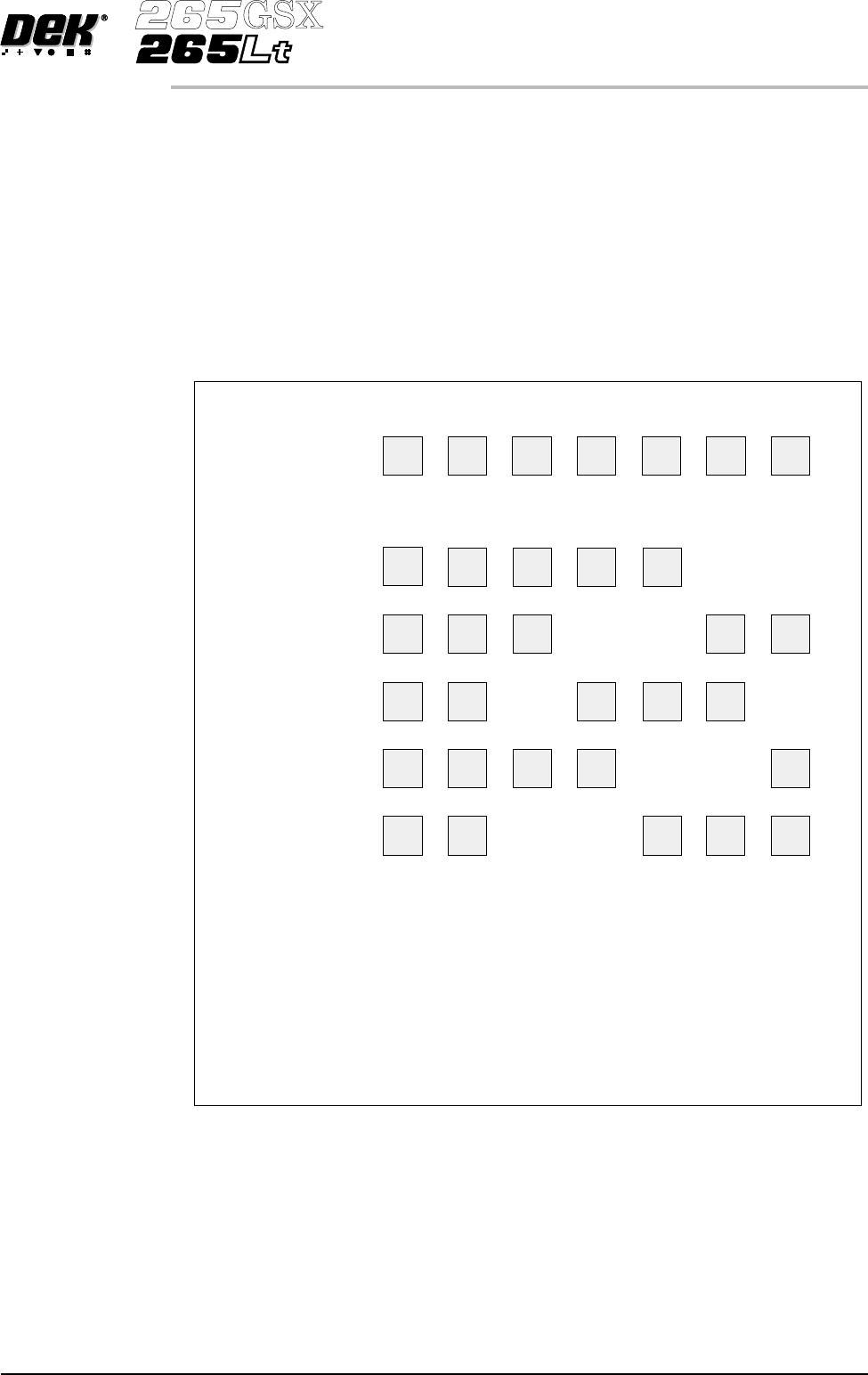
In the above example, 7 sites have been setup, with 2 given the priority of Every Cycle (EC)
and 5 given the priority of General (G). The min sites/cycle parameter is set at 5.
As there are 2 EC sites, this leaves 3 G sites to be inspected at each cycle as follows:
Cycle 1 - Sites 3, 4 and 5.
Cycle 2 - Sites 6, 7 and 3.
Cycle 3 - Sites 4, 5 and 6.
Cycle 4 - Sites 7, 3 and 4.
Cycle 5 - Sites 5, 6 and 7.
Cycle 6 - Process repeats.
Site 2 Site 3 Site 4 Site 5 Site 6 Site 7
EC
EC
EC
EC
EC EC
EC
EC
EC
EC
EC
EC
G
G
G GG
G
G
GG
G G G
G
G G
G
G G G G
Figure 8-8 Site Inspection Cycles
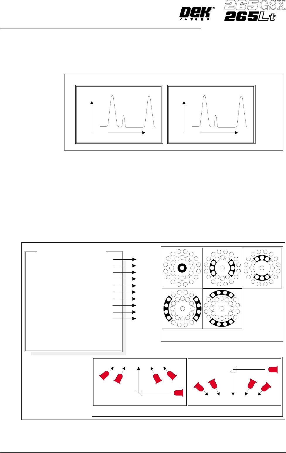
Histogram The Cognex card analyses the grey scale levels, of the pixels that make up the
site image. From thisinformation a histogram is produced, which can be used as
a visual aid to setting up 2Di inspection.
Lighting The lighting levels for 2Di inspection are software controlled. For a more
detailed description of the camera and optical unit refer to the Camera and
Vision Systems Module Chapter.
The GSX and Lt machines use either the silver or green cameras. The Horizon
and Infinity machines use only the green camera.
For the silver camera the lighting parameters and their functions are shown
below.
8.10 User Manual Software Version 6
2Di INSPECTION
MODULE OVERVIEW
Screen Histogram Board Histogram
No.ofPixels
Black
Screen
Aperture
Pa s t e
White
No.OfPixels
Black
Pa d
Board
Pa s t e
White
Grey Scale Level
Grey Scale Level
Figure 8-9 Screen and Board Histograms
8
8
8
8
8
8
8
8
8
8
-1.0
-1.5
2.0
2.0
Inspection Lighting Parameters
Screen Vertical
Screen Inner LR
Screen Inner FR
Screen Outer LR
Screen Outer FR
Board Vertical
Board Inner LR
Board Inner FR
Board Outer LR
Board Outer FR
Window Left
Window Top
Window Width
Window Height
A
B
C
D
E
A
B
C
D
E
NOTE
LR = Left and Right
FR=FrontandRear
Camera Lighting
Plan View Figure:
Screen Camera Lighting (Side View)
Prism
Outer
Inner
Inner
Vertical
Outer
LED
Board Camera Lighting (Side View)
Outer
Inner
Vertical
Inner
Outer
Prism
LED
Plan View of Camera Lighting LEDs
(Board or Screen)
A
B
C
D
E
Figure 8-10 Software Controlled Lighting - Silver Camera
For the green camera the lighting parameters and their functions are shown
below.
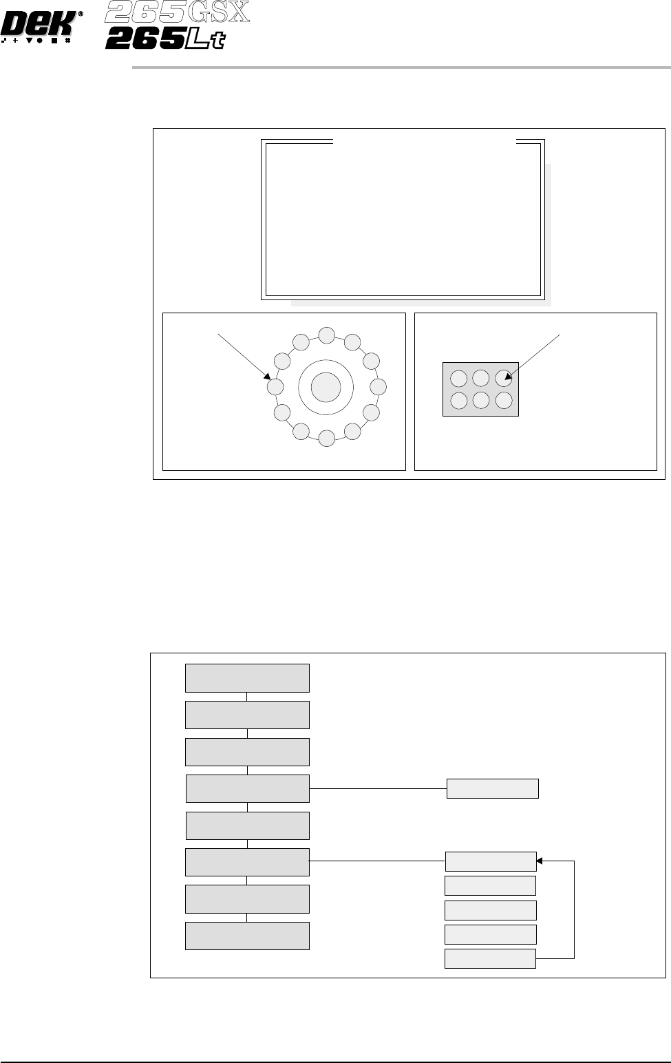
Inspection Setup Correct inspection setup is the key to effective inspection. By following the
steps of the setup sequence, shown in the summary below and the setup guide
over the page, effective inspection may be achieved.
Software Version 6 User Manual 8.11
2Di INSPECTION
MODULE OVERVIEW
8
8
8
8
-1.0
-1.5
2.0
2.0
Inspection Lighting Parameters
Screen Vertical
Screen Oblique
Board Vertical
Board Oblique
Window Left
Window Top
Window Width
Window Height
Oblique Lighting LED
Board and Screen Oblique Lighting
Direct Lighting LED
Board and Screen Direct Lighting
Figure 8-11 Software Controlled Lighting - Green Camera
Setup
Set Preferences
Edit Data
Load Product File
Inspect Setup
Edit Global
Edit Limits
Run
Inspect
Edit Site
Limit Options
Add Site
Learn Site
Learn Board
Auto Learn
Light Setup
Figure 8-12 Summary of Setup