Dek-265GSX-User-Manual.pdf.pdf - 第380页
12. Fill the remaining space between the secondary grid and the working edges of the wiper blades ensuring that the paste is level, (procedure below refers). 13. Fit paste cover to the unit. 14. Remove the transfer head …
5. Fill the cavity until the paste starts to flow back up through the primary grid,
extracting the nozzle slowly whilst continuing to fill. (This action fills the
hole left by the nozzle.)
6. Move to the next available centre hole, in the primary grid, that has not been
filled with paste. Repeat Steps 4 and 5.
7. Continue the above procedures until all the space below the primary grid is
topped up with paste.
NOTE
Ensure that there is little or no air bubbles trapped within the paste fill.
8. Re-fitthesecondaryProFlowgrid, wipers and end retainers (skis) to the unit.
9. Starting at one end of the centre row of holes in the secondary ProFlow grid,
insert the gun nozzle through the grid into the conditioning chamber area.
10. Fill the cavity until the paste starts to flow back up through the ProFlow grid,
extracting the nozzle slowly whilst continuing to fill. (This action fills the
hole left by the nozzle.)
11. Move to the next available centre hole, in the secondary grid, that has not
been filled with paste. Repeat Steps 9 and 10.
Software Version 6 User Manual 9.65
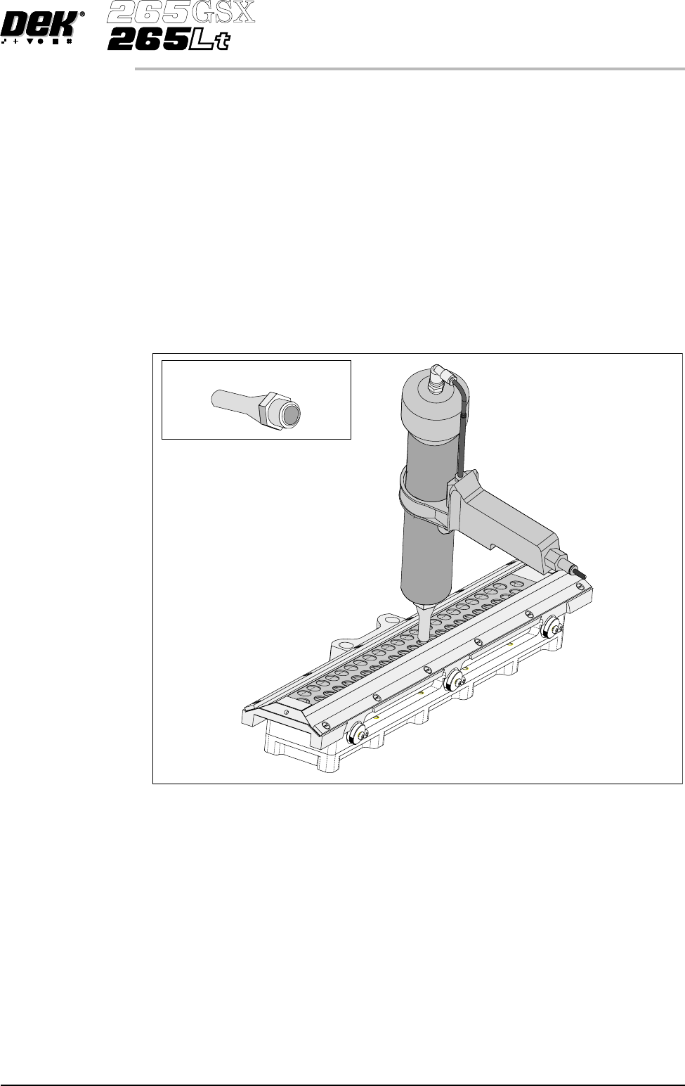
CONSUMABLE REPLENISHMENTS
PROFLOW
Long Recharging Nozzle
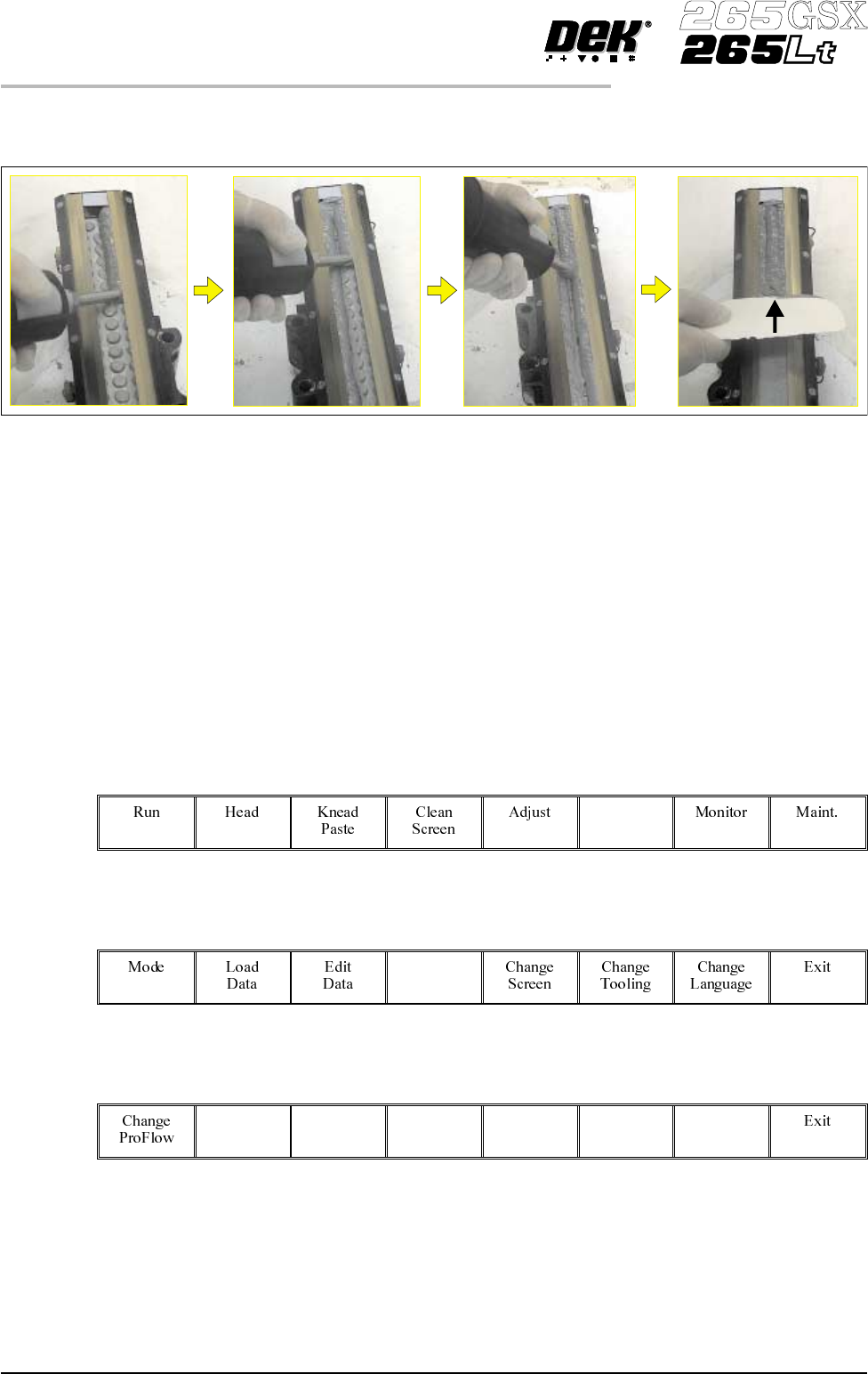
12. Fill the remaining space between the secondary grid and the working edges
ofthe wiper blades ensuring that the paste is level, (procedurebelowrefers).
13. Fit paste cover to the unit.
14. Remove the transfer head from the maintenance stand and fit the unit to the
ProFlow on the machine. (Refer to Technical Reference Manual, ProFlow
Chapter, Setting Up Procedures for detailed information on unit
removal/fitting.)
The transfer head can be replenished prior to and during a print run.
Prior to a Print Run The transfer head can be replenished prior to selecting Run.
1. If the ProFlow unit is in the home position continue with Step 2. If the
ProFlow unit is in the contact position go to Step 20.
2.
Select Setup (F6).
Setup
3.
Select Setup ProFlow (F4).
Setup
ProFlow
4.
Select Load Cassette (F4).
Load
Cassette
The message ‘Has the ProFlow unit’s base cover been removed?’ is
displayed.
5. If the ProFlow unit’s base cover is still fitted continue with Step 6. If the
ProFlow unit’s base cover has been removed go to Step 12.
9.66 User Manual Software Version 6
CONSUMABLE REPLENISHMENTS
PROFLOW
6.
Select Remove Cover (F8).
Remove
Cover
The message ‘Open the printer cover and remove the ProFlow unit’s
base cover’ is displayed.
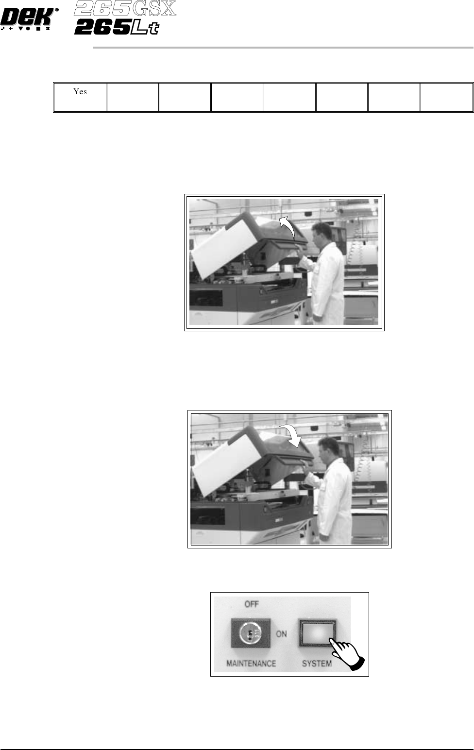
7. Open the printhead cover.
8. Remove the ProFlow unit’s base cover.
9. Close the front printhead cover.
10.
Press the System button.
Software Version 6 User Manual 9.67
CONSUMABLE REPLENISHMENTS
PROFLOW