Dek-265GSX-User-Manual.pdf.pdf - 第80页
Toggling State of Pins in an Area 18. Use the Left , Right , Up and Down keys (F4 - F7), to position the highlighted cursor over the required section. Left Right Up Down 19. Select Zoom (F1). Zoom NOTE The figures down t…
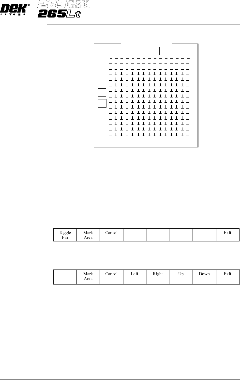
A close up view of the Fine Pitch Autoflex Matrix window is displayed:
NOTE
The figures down the right hand side of the template correspond to the figures on
the MMI matrix and represent the distance from the front edge of the board. The
figures across the top of the template are referenced to the centreline of the
board, where as the MMI matrix is referenced to the fiducial reference point on
the front edge of the board.
14.
Use the Left, Right, Up and Down keys (F4 - F7), to highlight the required
pin.
Left Right Up Down
15.
Select Toggle Pin (F1).
Toggle
Pin
16. Repeat Steps 14-15 for any other pins.
17. Go to Step 26.
Software Version 6 User Manual 1.63
MACHINE PROGRAMMING
STAGE 6F
Fine Pitch Autoflex Matrix
77.0
14.5
168.5
0 154
9
J
92.5
Toggling State of Pins in an Area
18.
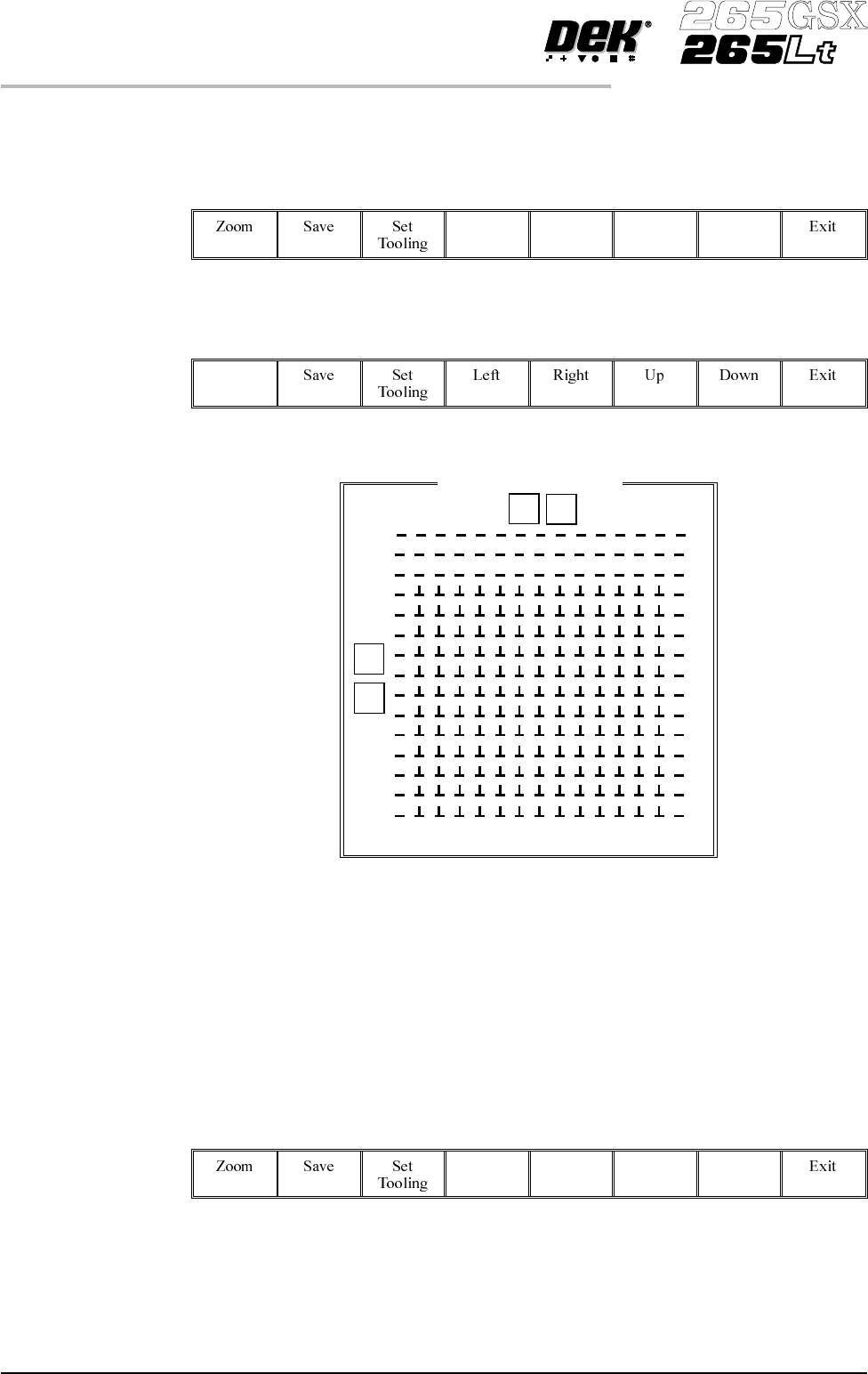
UsetheLeft,Right,UpandDownkeys(F4-F7),topositionthehighlighted
cursor over the required section.
Left Right Up Down
19.
Select Zoom (F1).
Zoom
NOTE
The figures down the right hand side of the template correspond to the figures on
the MMI matrix and represent the distance from the front edge of the board. The
figures across the top of the template are referenced to the centreline of the
board, where as the MMI matrix is referenced to the fiducial reference point on
the front edge of the board.
20.
Use the Left, Right, Up and Down keys (F4 - F7), to position the cursor at
one corner of the required area.
Left Right Up Down
1.64 User Manual Software Version 6
MACHINE PROGRAMMING
STAGE 6F
Fine Pitch Autoflex Matrix
77.0
14.5
168.5
0 154
9
J
92.5
21.
Select Mark Area (F2).
Mark
Area
22.
Use the Left, Right, Up and Down keys (F4 - F7), to position the cursor at
the opposite corner of the required area.
Left Right Up Down
23.
Select Toggle Area (F1).
Toggle
Area
24.
Select End Mark (F2).
End
Mark
25. Repeat Steps 20-24 for any other areas.
26.
Select Exit (F8).
Exit
27.
Select Save (F2).
Save
28.
Select Set Tooling (F3), pins all lower and setup for new configuration.
Set
Tooling
Software Version 6 User Manual 1.65
MACHINE PROGRAMMING
STAGE 6F