Dek-265GSX-User-Manual.pdf.pdf - 第288页
4. Enter parameters using the Next, Previous, Incr. and Decr. keys. Next Previous Incr. Decr. 5. Highlight site limit ID using the Next and Previous keys. Next Previous 6. Select Incr . Incr. 7. Using Next Limit or Previ…
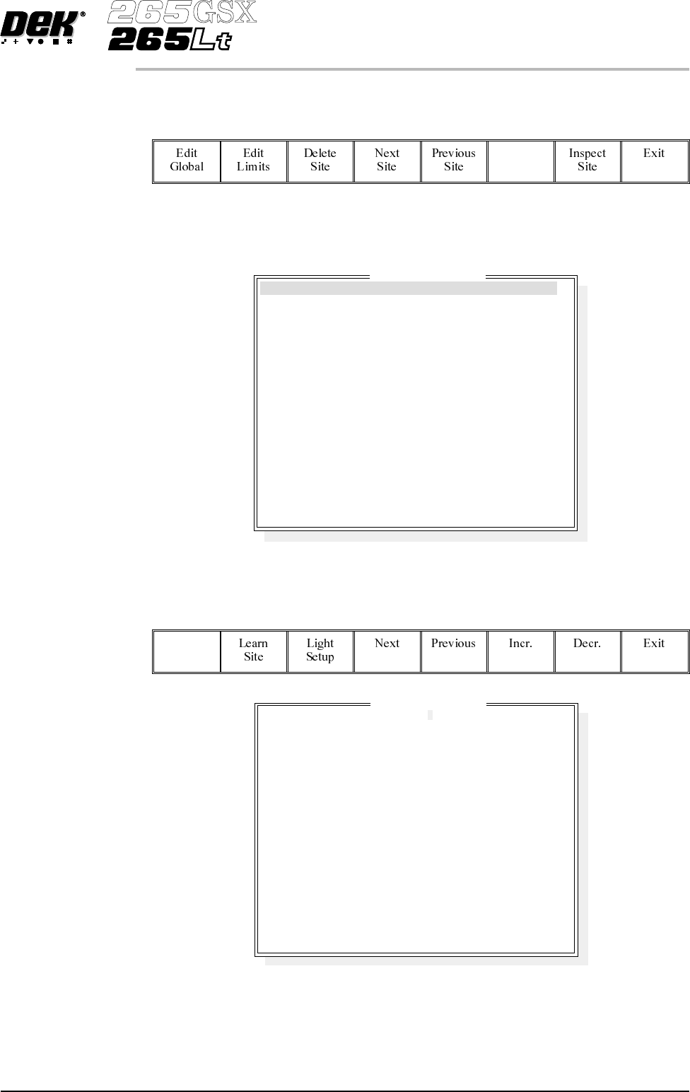
Edit Site 1.
Select Edit Site. The edit site parameters window is displayed and the site
name parameter is highlighted.
Edit
Site
NOTE
Delete site is only available if at least one site exists already. Next site and
previous site are only available if at least two sites exist already.
NOTE
Screen graphic and board graphic are only relevant to GSX/Lt machines.
2.
Select Add Site. The cursor flashes along side the site name parameter.
Add
Site
3.
Use the keyboard to enter the site name and press Enter.
NOTE
Site name may be any name up to 20 characters in length including spaces.
Software Version 6 User Manual 8.23
2Di INSPECTION
2Di SETUP
SITE 1
GENERAL
ADVANCED
ADVANCED
X and Y
COARSE
1.00
80.4 mm
86.4 mm
2.00 mm
2.00 mm
WHITE
0.00 mm
0.00 mm
BLACK
0.00 mm
0.00 mm
Edit Site Parameters
SITE NAME
SITE PRIORITY
STENCIL INSPECT TYPE
BOARD INSPECT TYPE
SITE ALIGNMENT
LIMIT SET ID
PASTE SCALING
SITE X COORD
SITE Y COORD
SITE WIDTH
SITE HEIGHT
SCREEN GRAPHIC
SCREEN GRAPHIC X
SCREEN GRAPHIC Y
BOARD GRAPHIC
BOARD GRAPHIC X
BOARD GRAPHIC Y
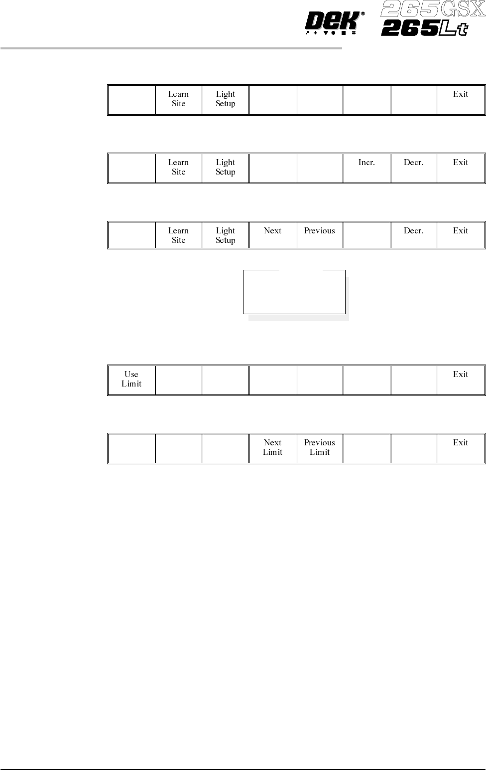
4.
Enter parameters using the Next, Previous, Incr. and Decr. keys.
Next Previous Incr. Decr.
5.
Highlight site limit ID using the Next and Previous keys.
Next Previous
6.
Select Incr.
Incr.
7.
Using Next Limit or Previous Limit keys, highlight the coarse limit set
created in either add limits or edit limits.
Next
Limit
Previous
Limit
8.
Select Use Limit.
Use
Limit
9. Measure the X and Y dimensions of the required site from the board or
screen.
NOTE
For the initial setup of 2Di use a single site. After the setup is complete add auto
learn features if required.
8.24 User Manual Software Version 6
2Di INSPECTION
2Di SETUP
DEFAULT
FINE
COARSE
Limit Sets
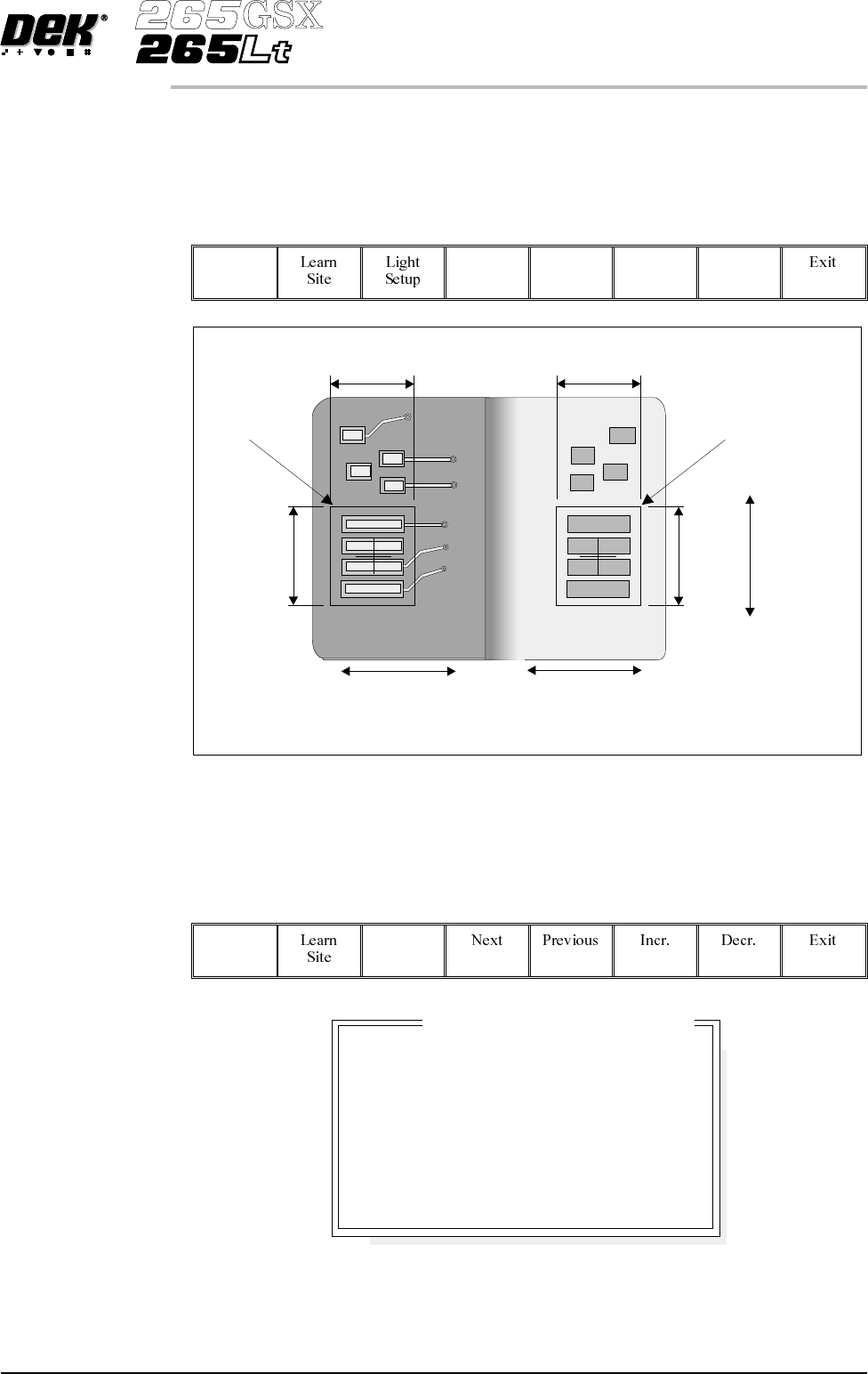
10.
Set site X coord and site Y coord, using the Next, Previous, Incr. and Decr.
keys, to display the site on the monitor. Adjust site width, site height, screen
grahic (if applicable), site X coord, and site Y coord, using the Next,
Previous, Incr. and Decr. keys, to position the site graphic over the screen,
as shown.
Next Previous Incr. Decr.
NOTE
Adjust the site height and site width so that the board site is large enough to
cover the pads.
Lighting Setup 1.
Select Light Setup.
Light
Setup
Software Version 6 User Manual 8.25
2Di INSPECTION
2Di SETUP
Screen Site
Board Site
Site
Height
Site
Height
Site
Width
Site
Width
Site
Y Coord
Movement
Site
X Coord
Movement
Site
X Coord
Movement
8
8
8
8
-1.5
-1.5
3.0
3.0
mm
mm
mm
mm
Inspection Lighting Parameters
Screen Vertical
Screen Oblique
Board Vertical
Board Oblique
Window Left
Window Top
Window Width
Window Height
Figure 8-14 Lighting Parameters - Green Camera